Residual current circuit breakers (RCCB)
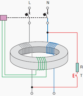
The operating principle of the residual current release is basically the detection of an earth fault current, by means of a toroid transformer which embraces all the live conductors, included the neutral if distributed.

In absence of an earth fault, the vectorial sum of the currents IΔ is equal to zero.
In case of an earth fault, if the IΔ value exceeds the rated residual operating current IΔn, the circuit at the secondary side of the toroid sends a command signal to a dedicated opening coil causing the tripping of the circuit-breaker.
Classifications of RCDs
A first classification of RCDs can be made according to the type of the fault current they can detect:
- AC type: the tripping is ensured for residual sinusoidal alternating currents, whether suddenly applied or slowly rising;
- A type: tripping is ensured for residual sinusoidal alternating currents and residual pulsating direct currents, whether suddenly applied or slowly rising;
- B type: tripping is ensured for residual direct currents, for residual sinusoidal alternating currents and residual pulsating direct currents, whether suddenly applied or slowly rising.
Another classification referred to the operating time delay is:
- Undelayed type;
- Time delayed S-type.
RCDs can be coupled, or not, with other devices; it is possible to distinguish among:
- Pure residual current circuit-breakers (RCCBs)
They have only the residual current release and can protect only against earth fault. They must be coupled with thermomagnetic circuit breakers or fuses, for the protection against thermal and dynamical stresses; - Residual current circuit-breakers with overcurrent protection (RCBOs)
They are the combination of a thermomagnetic circuit-breaker and a RCD; for this reason, they provide the protection against both overcurrents as well as earth fault current; - Residual current circuit-breakers with external toroid
They are used in industrial plants with high currents.
They are composed by a release connected to an external toroid with a winding for the detection of the residual current; in case of earth fault, a signal commands the opening mechanism of a circuit breaker or a line contactor.
RCD Operation
Given IΔn the operating residual current, a very important parameter for residual current devices is the residual non-operating current, which represents the maximum value of the residual current which does not cause the circuit-breaker trip; it is equal to 0.5 IΔn.
Therefore, it is possible to conclude that:
- for IΔ < 0.5⋅IΔn the RCD shall not operate;
- for 0.5⋅IΔn < IΔ < IΔn the RCD could operate;
- for IΔ > IΔn the RCD shall operate.
For the choice of the rated operating residual current, it is necessary to consider, in addition to the coordination with the earthing system, also the whole of the leakage currents in the plant.
Their vectorial sums on each phase shall not be greater than 0.5⋅IΔn. in order to avoid unwanted tripping.
Discrimination between RCDs
The Standard IEC 60364-5-53 states that discrimination between residual current protective devices installed in series may be required for service reasons, particularly when safety is involved, to provide continuity of supply to the parts of the installation not involved by the fault, if any.
There are two types of discrimination between RCDs:
Horizontal discrimination
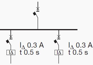
It provides the protection of each line by using a dedicated residual current circuit-breaker; in this way, in case of earth fault, only the faulted line is disconnected, since the other RCDs do not detect any fault current.
However, it is necessary to provide protective measures against indirect contacts in the part of the switchboard and of the plant upstream the RCD;
Vertical discrimination
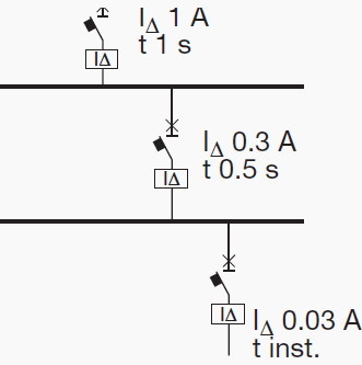
It is realized by using RCDs connected in series.
Conditions
According to IEC 60364-5-53, to ensure discrimination between two residual current protective devices in series, these devices shall satisfy both the following conditions:
- The non-actuating time-current characteristic of the residual current protective device located on the supply side (upstream) shall lie above the total operating time-current characteristic of the residual current protective device located on the load side (downstream);
- The rated residual operating current on the device located on the supply side shall be higher than that of the residual current protective device located on the load side.
The Non-actuating time-current characteristic
The non-actuating time-current characteristic is the curve reporting the maximum time value during which a residual current greater than the residual non-operating current (equal to 0.5.IΔn) involves the residual current circuit breaker without causing the tripping.
- For S type residual current circuit-breakers, located on the supply side, (complying with IEC 61008-1 and IEC 61009), time-delayed type, by choosing general type circuit-breakers located downstream with IΔn equal to one third of IΔn of the upstream ones;
- For electronic residual current releases by choosing the upstream device with time and current thresholds directly greater than the downstream device, keeping carefully into consideration the tolerances.
Resource: Electrical Installation Handbook (part II) – ABB
Copyright Notice
This technical article is protected by U.S. and international copyright laws. Reproduction and distribution of PDF version of this technical article to websites such as Linkedin, Scribd, Facebook and others without written permission of the sponsor is illegal and strictly prohibited.© EEP-Electrical Engineering Portal.
Related electrical guides & articles
Premium Membership
Edvard Csanyi
Hi, I'm an electrical engineer, programmer and founder of EEP - Electrical Engineering Portal. I worked twelve years at Schneider Electric in the position of technical support for low- and medium-voltage projects and the design of busbar trunking systems.I'm highly specialized in the design of LV/MV switchgear and low-voltage, high-power busbar trunking (<6300A) in substations, commercial buildings and industry facilities. I'm also a professional in AutoCAD programming.
Profile: Edvard Csanyi







I´ve a installation with motor driver´s. If I start all driver´s at the same time I trip a Feeder RCD, so now I´m evaluating to separate this driver´s in groups and put one RCD to protect this group of branch circuit, and put a type A RCD to feeder protection. You think this is a good decision to avoid a RCD trip when driver´s start´s? Thank you in advanced I hear your suggestions.
I HAVE STEP DOWN TRANSFORMER 66/11KV ITS CONNECTION IS (YND11) SUPPLY TWO FEEDERS 11KV EARTH FAULT OCCUR ON ONE OF THEM BUT EARTH FAULT PROTECTION DOES NOT RESPONSE WHAT THE LIKELY CAUSE THANKS FOR HELP
hi all
I can’t find difference between type A and B because they both ” tryping ensure residual sinusoidal alternating currents and residual pulsating direct currents, whether suddenly applied or slowly rising”
plz if someone help me for the difference.
http://www.etci.ie/docs/ET214.pdf. frnds, i found another one on RCDs …thanks to google guru.
Thanks for this, nice guide! I’ll take a look at it.
Edvard , thank u for this informative article..
Could you please define/list the ” indirect contacts ” you mentioned in the article?
The measures against indirect contacts in the part of the switchboard should be:
– automatic disconnection of the supply (put protective device which automatically disconnect the supply to the circuit so that the touch voltage on the exposed conductive part does not persist for a time sufficient to cause a risk of harmful physiological effect for human beings)
– supplementary insulation or reinforced insulation
– electrical separation, by using an isolating transformer to supply the circuit;
– earth-free local equipotential bonding
Hi All,
1. can any body please explain about space to height ratio and its significance in lighting designing. After arrangements of fittings how to check whether achieved Space to height ratio is correct or not.
2. What is X, X/2 distance of arrangement. What its significance in lighting design?
Plz help me…!
I’m not sure I can follow you, you are asking about lighting?
This is article about RCDs, not lighting. Please post your question to some of articles related to lighting.
thnk u very much