
Estimated Study Time: 5 minutes
Two basic types
There are two basic types of combustion turbines (CTs) other than the microturbines:
- The heavy frame industrial turbines and
- The aeroderivative turbines. The heavy frame systems are derived from similar models that were steam turbine designs.
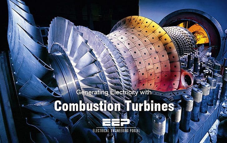
As can be identified from the name, they are of very heavy construction. The aeroderivative systems have a design history from the air flight industry, and are of a much lighter and higher speed design.
These types of turbines, although similar in operation, do have some significant design differences in areas other than physical size. These include areas such as turbine design, combustion areas, rotational speed, and air flows.
Although these units were not originally designed as a “distributed generation” technology, but more so for central station and large co-generation applications, the technology is beginning to economically produce units with ratings in the hundreds of kilowatts and single-digit megawatts.
Most applications of the turbines as distributed generation will operate on either natural gas or fuel oil. The operating characteristics between the two systems can best be described in tabular form as shown in Figure 2.
Figure 1 – Basic combustion turbine operating characteristics
| Heavy frame | Aeroderivative | |
| Size (Same general rating) | Large | Compact |
| Shaft speed | Synchronous | Higher speed (coupled through a gear box) |
| Air flow | High (lower compression) | Lower (high compression) |
| Start-up time | 15 minutes | 2-3 minutes |
The combustion turbine unit consists of three major mechanical components: a compressor, a combustor, and a turbine.
The compressor takes the input air and compresses it, which will increase the temperature and decrease the volume per the Brayton Cycle. The fuel is then added and the combustion takes place in the combustor, which increases both the temperature and volume of the gaseous mixture, but leaves the pressure as a constant. This gas is then expanded through the turbine where the power is extracted through the decrease in pressure and temperature and the increase in volume.

Other equipment modifications and improvements can be incorporated into these types of combustion turbines such as multistage turbines with fuel re-injection, inter-cooler between multistage compressors, and steam/water injection.
Typical heat rates for simple cycle combustion turbines vary across manufacturers, but are in a range from 11,000 to 20,000 BTU/kWh. However, these numbers decrease as recuperation and co-generation are added. CTs typically have a starting reliability in the 99% range and operating reliability approaching 98%. The operating environment has a major effect on the performance of combustion turbines.
The elevation at which the CT is operating has a degradation factor of around 3.5% per 1000 ft of increased elevation and the ambient temperature has a similar degradation per 10°increase.

Figure 2 shows a block diagram of a simple cycle combustion turbine with a recuperator (left) and a combustion turbine with multistage turbine and fuel re-injection (right).
Gas turbine in power plant (VIDEO)
Cant see this video? Click here to watch it on Youtube.
Reference: The electric power engineering handbook – L.L. Grigsby (Purchase hardcover book from Amazon)


Edvard Csanyi
Hi, I'm an electrical engineer, programmer and founder of EEP - Electrical Engineering Portal. I worked twelve years at Schneider Electric in the position of technical support for low- and medium-voltage projects and the design of busbar trunking systems.I'm highly specialized in the design of LV/MV switchgear and low-voltage, high-power busbar trunking (<6300A) in substations, commercial buildings and industry facilities. I'm also a professional in AutoCAD programming.
Profile: Edvard Csanyi

Good information thank you
Great work
Please give us some note about DG sets using IC engine
Beautiful video!! Congratulations!!