
Estimated Study Time: 9 minutes
Laboratory tests
Benjamin Franklin – The man who dared to fly his kite in a thunder storm! In this technical article laboratory tests and test equipment needed to assess the performance of insulating materials and equipment are discussed.
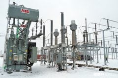
 Generation of high voltages in the lab (AC/DC, switching and lightning impulse) - photo credit: @HighVoltage_UoM via Twitter
Laboratory testing attempts to simulate the voltage conditions that the apparatus may experience on the power system. These voltages include the normal AC or DC system voltages and switching and lightning impulse voltages.
Tests can be performed to obtain the failure or flashover voltage or otherwise to obtain the withstand voltage of an apparatus.
1. Power frequency voltage and current (AC)
In an AC network the equipment is continuously subjected to full power frequency voltage. The equipment should therefore be able to withstand power normal frequency voltage, allowing for some overvoltage.
In a high voltage laboratory the test transformers steps up the voltage from a lower voltage (220 V or 11 kV) to the desired voltage level. All laboratory tests are single phase and the low voltage side of the transformer is supplied via a regulating transformer to be able to adjust the magnitude of the output high voltage.
A typical AC high voltage set-up is shown in Figure 1.
The following features should be noted:
- Ground plane: The high voltage is generated with respect to the laboratory ground, a low impedance sheet, connected to an earth electrode.
- Voltage divider: The voltage is measured with a resistive or capacitive voltage divider.
Typical designs of high voltage test transformers are shown in Figure 2(a). In the design on the right an insulated tank (a resin impregnated paper cylinder) is used and a bushing is not required, as is shown in Figure 2(b).

Test transformers can be used in cascade connections as is shown in Figure 3. Each unit has 3 windings: a primary (low voltage), a secondary (high voltage) and a tertiary (low voltage) winding. The tertiary has the same rating as the primary winding; however, it is insulated for high voltage.
The tertiary winding is used to supply the primary of the next unit. The tanks of the second and third units are insulated for high voltage and are mounted on insulators.

The method when performing AC tests is to increase the voltage gradually until flashover occurs. The voltage just before flashover is the flashover voltage.
2. Direct current (DC)
DC tests are used mainly to do “pressure tests” on high voltage cables. Although the cables operate with AC, AC testing is not practical. The high capacitance of the cables necessitates AC test sets with a high kVA rating to be able to supply the capacitive current. In the case of DC, once the cable is charged, only the losses have to be supplied.
DC test sets usually consist of half wave rectification, using HV selenium rectifiers. A typical DC test set-up is shown in Figure 4.
An AC high voltage test transformer is again supplied via a variac and a rectifier is used together with a filter capacitor C to limit the ripple to acceptable values. The earthing switch ES is a safety feature and closes automatically when the power is switched off to discharge the capacitor C.
Note that the peak inverse voltage required of the rectifier is 2 Vm.

Doubling and multiplier circuits (as used in TV’s and household appliances) are also used to obtain an even higher voltage. A typical Cockcroft-Walton (in Germany: Greinacher) doubling circuit is shown in Figure 5.

3. Lightning and switching impulses
Power system is also subjected to single overvoltage pulses, due to lightning and switching. In the field these transients can take on many different wave shapes. Standard impulse wave has been defined as shown in Figure 7.
The actual definition is more precise, but for lightning impulses, T1 is 1.2 μs and T2 is 50 μs. The standard lightning impulse is described as a 1.2/ 50 μs wave. The standard switching impulse is a 250/ 2500 μs wave.

During transformer tests it is sometimes required to chop the impulse to obtain a high dv/dt, in order to test the inter-turn insulation.
The Impulse generator
In order to generate a wave with the required shape, circuits similar to that shown in Figure 8 are used. A capacitor C1 is charged via a current limiting resistor Rs, from a HV DC source similar to those shown in Figures 4 and 5.
As the DC voltage is raised slowly the stress across the spark gap G increases until the air in the gap breaks down. Capacitor C1 now discharges into the circuit consisting of C2, R1 and R2. The voltage appearing across the test object has the desired shape.
There are two possible positions for R1 as is shown in Figure 8.
It is possible to design a multi stage impulse generator by charging the various stages in parallel and by discharging in series. This principle was invented by Marx in 1923. A typical circuit is shown in Figure 9.
Note that it is possible to trigger the lowest gap of the generator artificially. The resulting transient causes the other gaps to flash over simultaneously. Impulse generators are specified in terms of the peak voltage and the stored energy.
The generator shown in Figure 10 is a 1.4 MV, 16 kJ generator.

Reference // High Voltage Engineering Practice and Theory by Dr JP Holtzhausen and Dr WL Vosloo
Related electrical guides & articles


Edvard Csanyi
Hi, I'm an electrical engineer, programmer and founder of EEP - Electrical Engineering Portal. I worked twelve years at Schneider Electric in the position of technical support for low- and medium-voltage projects and the design of busbar trunking systems.I'm highly specialized in the design of LV/MV switchgear and low-voltage, high-power busbar trunking (<6300A) in substations, commercial buildings and industry facilities. I'm also a professional in AutoCAD programming.
Profile: Edvard Csanyi

Hi, Nice to see the articles. Can you please clarify why impulse voltage is applicable only above 300 kV.
my dear,
Thank you for the above explain,But if one of the capacitors in any stage was damaged,What happens when you raise a voltage?
best wishes