Generating unit complexity
Generating unit is a pretty complex system made up of the generator stator winding, its transformer and unit transformer (if present), the rotor with its field winding and excitation system, and the prime mover with its associated auxiliaries.

Many different faults can occur within this generating unit system for which a wide range of electrical and mechanical protection is required.
This technical article deals with generator earthing methods and only the stator earth fault protection.
- Generator earthing
- Earth fault protection
1. Generator earthing
The neutral point of a generator is usually earthed to facilitate the protection of the stator winding and associated system. Earthing also prevents damaging transient overvoltages in the event of an arcing earth fault or ferroresonance.
For HV generators, impedance is usually inserted in the stator earthing connection to limit the magnitude of the earth fault current.
There is a wide variation in the earth fault current chosen, common values being:
- rated current
- 200A-400A (low impedance earthing)
- 10A-20A (high impedance earthing)
The main methods of impedance-earthing a generator are shown in Figure 1. Low values of earth fault current may limit the damage caused from a fault, but they simultaneously make detection of a fault towards the stator winding star point more difficult.
Where a step-up transformer is applied, the generator and the lower voltage winding of the transformer can be treated as an isolated system that is not influenced by the earthing requirements of the power system.
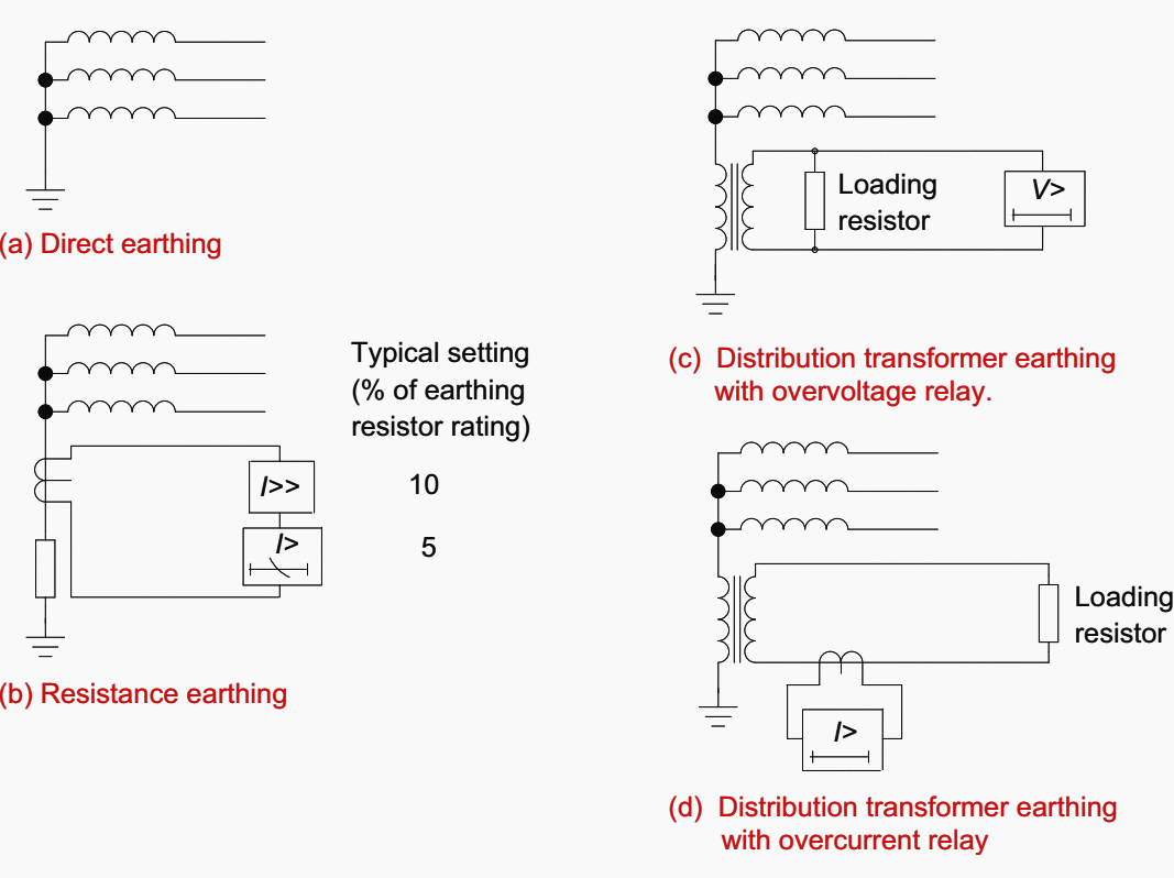

An earthing transformer or a series impedance can be used as the impedance. If an earthing transformer is used, the continuous rating is usually in the range of 5-250kVA. The secondary winding is loaded with a resistor of a value which, when referred through the transformer ratio, will pass the chosen short-time earth-fault current.
This is typically in the range of 5-20 A.
This is the basis of the design, and in practice values of between 3-5 Ico are used.
It is important that the earthing transformer never becomes saturated. Otherwise a very undesirable condition of ferroresonance may occur.
The normal rise of the generated voltage above the rated value caused by a sudden loss of load or by field forcing must be considered, as well as flux doubling in the transformer due to the point-on-wave of voltage application.
It is sufficient that the transformer be designed to have a primary winding knee-point e.m.f. equal to 1.3 times the generator rated line voltage.
2. Earth fault protection
Earth fault protection must be applied where impedance earthing is employed that limits the earth fault current to less than the pick-up threshold of the overcurrent and/or differential protection for a fault located down to the bottom 5% of the stator winding from the star-point.
The type of protection required will depend on the method of earthing and connection of the generator to the power system.
2.1 Direct-Connected Generators
A single direct-connected generator operating on an isolated system will normally be directly earthed. However, if several direct-connected generators are operated in parallel, only one generator is normally earthed at a time.
The following paragraphs describe the methods available:
2.1.1 Neutral Overcurrent Protection
With this form of protection, a current transformer in the neutral-earth connection energizes an overcurrent relay element. This provides unrestricted earth-fault protection and so it must be graded with feeder protection.
The relay element will therefore have a time-delayed operating characteristic.
Grading (or grading margin) must be carried out in accordance with the following principles:
1. Circuit Breaker Interrupting Time
The circuit breaker interrupting the fault must have completely interrupted the current before the discriminating relay ceases to be energized. The time taken is dependent on the type of circuit breaker used and the fault current to be interrupted.
2. Relay Timing Error
All relays have errors in their timing compared to the ideal characteristic as defined in IEC 60255. For a relay specified to IEC 60255, a relay error index is quoted that determines the maximum timing error of the relay.
The timing error must be taken into account when determining the grading margin.
3. Overshoot
When the relay is de-energized, the operation may continue for a little longer until any stored energy has been dissipated.
For example, an induction disc relay will have stored kinetic energy in the motion of the disc; static relay circuits may have energy stored in capacitors. Relay design is directed to minimizing and absorbing these energies, but some allowance is usually necessary.
The overshoot time is defined as the difference between the operating time of a relay at a specified value of input current and the maximum duration of input current, which when suddenly reduced below the relay operating level, is insufficient to cause relay operation.
4. CT Errors
Current transformers have phase and ratio errors due to the exciting current required to magnetize their cores. The result is that the CT secondary current is not an identical scaled replica of the primary current.
5. Final Margin
After allowances have been made for circuit breaker interrupting time, relay timing error, overshoot and CT errors, the discriminating relay must just fail to complete its operation.
Some extra safety margin is required to ensure that relay operation does not occur.
The setting should not be more than 33% of the maximum earth fault current of the generator, and a lower setting would be preferable, depending on grading considerations.
2.1.2 Sensitive Earth Fault Protection
This method is used in the following situations:
- Direct-connected generators operating in parallel.
- Generators with high-impedance neutral earthing, the earth fault current being limited to a few tens of amps.
- Installations where the resistance of the ground fault path is very high, due to the nature of the ground.
In these cases, conventional earth fault protection is of little use.
The earth fault (residual) current can be obtained from the residual connection of line CTs, a line-connected CBCT, or a CT in the generator neutral. The latter is not possible if directional protection is used. The polarising voltage is usually the neutral voltage displacement input to the relay, or the residual of the three-phase voltages, so a suitable VT must be used.
For Petersen Coil earthing, a wattmetric technique can also be used.
When being driven by residually-connected phase CTs, the protection must be stabilised against incorrect tripping with transient spill current in the event of asymmetric CT saturation when phase fault or magnetising inrush current is being passed.
Stabilizing techniques include the addition of relay circuit impedance and/or the application of a time delay. Where the required setting of the protection is very low in comparison to the rated current of the phase CTs, it would be necessary to employ a single CBCT for the earth fault protection to ensure transient stability.
Since any generator in the paralleled group may be earthed, all generators will require to be fitted with both neutral overcurrent protection and sensitive directional earth fault protection.
The setting of the sensitive directional earth fault protection is chosen to coordinate with generator differential protection and/or neutral voltage displacement protection to ensure that 95% of the stator winding is protected.
Figure 2 illustrates the complete scheme, including optional blocking signals where difficulties in coordinating the generator and downstream feeder earth-fault protection occur.


For cases (b) and (c) above, it is not necessary to use a directional facility. Care must be taken to use the correct Relay Characteristic Angle (RCA) setting – for instance, if the earthing impedance is mainly resistive, this should be 0°.
On insulated or very high impedance earthed systems, an RCA of –90° would be used, as the earth fault current is predominately capacitive.
Hence earth faults on the external system do not result in relay operation. However, the current flowing from the system into a winding earth-fault causes relay operation. It will not operate on the earthed machine, so other types of earth-fault protection must also be applied.
All generators must be so fitted since any can be operated as the earthed machine.
2.1.3 Neutral Voltage Displacement Protection
In a balanced network, the addition of the three phase-earth voltages produces a nominally zero residual voltage, since there would be little zero-sequence voltage present.
Any earth fault will set up a zero-sequence system voltage, which will give rise to a non-zero residual voltage.
This can be measured by a suitable relay element. The voltage signal must be derived from a VT that is suitable – i.e. it must be capable of transforming zero-sequence voltage, so 3-limb types and those without a primary earth connection are not suitable.
This unbalance voltage provides a means of detecting earth faults.
As the protection is still unrestricted, the voltage setting of the relay must be greater than the effective setting of any downstream earth fault protection. It must also be time-delayed to co-ordinate with such protection.
Sometimes, a second high-set element with a short time delay is used to provide fast-acting protection against major winding earth faults.
Figure 3 illustrates the possible connections that may be used.


2.2 Indirectly-Connected Generators
As noted at the beginning of this article, a directly-earthed generator-transformer unit cannot interchange zero-sequence current with the remainder of the network, and hence an earth fault protection grading problem does not exist.
The following paragraphs detail the protection methods for the various forms of impedance earthing of generators:
2.2.1 High Resistance Earthing – Neutral Overcurrent Protection
A current transformer mounted on the neutral-earth conductor can drive an instantaneous and/or time-delayed overcurrent relay element, as shown in Figure 4 below.
It is impossible to provide protection for the whole of the winding, and Figure 4 also details how the percentage of winding covered can be calculated. For a relay element with an instantaneous setting, protection is typically limited to 90% of the winding.
A time-delayed relay is more secure in this respect, and it may have a setting to cover 95% of the stator winding.


Since the generating units under consideration are usually large, instantaneous and time-delayed relay elements are often applied, with settings of 10% and 5% of maximum earth fault current respectively. This is the optimum compromise in performance.
The portion of the winding left unprotected for an earth fault is at the neutral end. Since the voltage to earth at this end of the winding is low, the probability of an earth fault occurring is also low.
Hence additional protection is often not applied.
2.2.2 Distribution Transformer Earthing Using a Current Element
In this arrangement, shown in Figure 5(a), the generator is earthed via the primary winding of a distribution transformer. The secondary winding is fitted with a loading resistor to limit the earth fault current.
The relay element response to the third harmonic current should be limited to prevent incorrect operation when a sensitive setting is applied.


– Protection using a current element
As discussed in the above section ”High Resistance Earthing – Neutral Overcurrent Protection”, the protection should be time delayed when a sensitive setting is applied, in order to prevent mal-operation under transient conditions.
It also must grade with generator VT primary protection (for a VT primary earth fault). An operation time in the range 0.5s-3s is usual.
Less sensitive instantaneous protection can also be applied to provide fast tripping for a heavier earth fault condition.
2.2.3 Distribution Transformer Earthing Using a Voltage Element
Earth fault protection can also be provided using a voltage-measuring element in the secondary circuit instead. The setting considerations would be similar to those for the current operated protection but transposed to voltage.
The circuit diagram is shown in Figure 6.


– Protection using a voltage element
Application of both voltage and current operated elements to a generator with distribution transformer earthing provides some advantages. The current operated function will continue to operate in the event of a short-circuited loading resistor and the voltage protection still functions in the event of an open-circuited resistor.
However, neither scheme will operate in the event of a flashover on the primary terminals of the transformer or of the neutral cable between the generator and the transformer during an earth fault.
A CT could be added in the neutral connection close to the generator, to energize a high-set overcurrent element to detect such a fault, but the fault current would probably be high enough to operate the phase differential protection.
2.2.4 Neutral Voltage Displacement Protection
This can be applied in the same manner as for direct-connected generators. The only difference is that there are no grading problems as the protection is inherently restricted.
A sensitive setting can therefore be used, enabling cover of up to 95% of the stator winding to be achieved.
2.3 Restricted Earth Fault Protection
This technique can be used on small generators not fitted with differential protection to provide fast-acting earth fault protection within a defined zone that encompasses the generator.
However, in contrast to transformer REF protection, both biased low-impedance and high-impedance techniques can be used.
2.3.1 Low-Impedance Biased REF Protection
This is shown in Figure 7. The main advantage is that the neutral CT can also be used in a modern relay to provide conventional earth-fault protection and no external resistors are used.
Relay bias is required, but the formula for calculating the bias is slightly different and also shown in Figure 7.
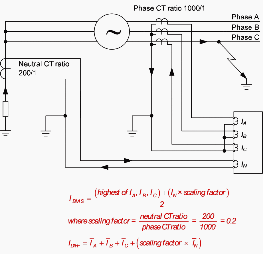

The initial bias slope is commonly set to 0% to provide maximum sensitivity and applied up to the rated current of the generator. It may be increased to counter the effects of CT mismatch. The bias slope above generator rated current is typically set to 150% of the rated value.
The initial current setting is typically 5% of the minimum earth fault current for a fault at the machine terminals.
2.3.2 High Impedance REF Protection
The same technique as of high impedance differential protection can be used for earth-fault protection of a generator, using three residually connected phase CTs balanced against a similar single CT in the neutral connection.
The usual requirements in respect of stabilizing resistor and non-linear resistor to guard against excessive voltage across the relay must be taken, where necessary.
2.4 Earth Fault Protection for the Entire Stator Winding
All of the methods for earth fault protection detailed so far leave part of the winding unprotected. In most cases, this is of no consequence as the probability of a fault occurring in the 5% of the winding nearest the neutral connection is very low, due to the reduced phase to earth voltage.
However, a fault can occur anywhere along the stator windings in the event of insulation failure due to localized heating from a core fault.
In cases where protection for the entire winding is required, perhaps for alarm only, there are various methods available:
2.4.1 Measurement of Third Harmonic Voltage
One method is to measure the internally generated third harmonic voltage that appears across the earthing impedance due to the flow of third harmonic currents through the shunt capacitance of the stator windings etc.
Hence, a conventional earth-fault scheme should be used in conjunction with a third harmonic scheme, to provide overlapping cover of the entire stator winding.
The measurement of third harmonic voltage can be taken either from a star-point VT or the generator line VT. In the latter case, the VT must be capable of carrying residual flux, and this prevents the use of 3-limb types.
If the third harmonic voltage is measured at the generator star point, an undervoltage characteristic is used.
An overvoltage characteristic is used if the measurement is taken from the generator line VT. For effective application of this form of protection, there should be at least 1% third harmonic voltage across the generator neutral earthing impedance under all operating conditions.
A problem encountered is that the level of third harmonic voltage generated is related to the output of the generator. The voltage is low when generator output is low.
2.4.2 Use of Low-Frequency Voltage Injection
Another method for protecting the entire stator winding of a generator is to deploy signal injection equipment to inject a low-frequency voltage between the stator star point and earth.
It is also an appropriate method to apply to variable speed synchronous machines. Such machines may be employed for variable speed motoring in pumped-storage generation schemes or for starting a large gas turbine prime mover.
Reference // Network Protection and Automation Guide by Alstom Grid







What are the effects on power quality when 20 Hz signal is getting mixed with 50 Hz voltage in generator for 100% stator earth fault protection ? Upto how much distance this 20 Hz signal can travel from generator ?
It’s useful site good knowledge gain.
Thank you so much very interested and much appreciated.
OUR GENERATOR WHICH IS BEING USED AS PRIME POWER FOR THE CAMP TRIPPING WHEN NEUTRAL IS GROUNDED. COULD YOU PLEASE CLARIFY ABOUT THE FAULT OR PROVIDE ME SOME HINTS TO LOCATE THE FAULT.
Really very interesting and knowledgeable
A lot of knowledge has been gained in this website. Thanks u sir
Thank you very much and I an anxiously waiting because I am electrical engineer
Thanks for publishing good relevant application oriented articles. For Building projects,
when LV DG sets are paralleled ,what are the issues especially about neutral earthing for Alternators ?
How do we manage ? Also about 11KV DG sets .
CS Nambisan
It’s useful site good knowledge gain.
I wanted to pay to get more access to your information. But you are forcing me to use PayPal to register. I will not do that. I have real issues with their services and steadfastly refuse to do business with them. So, I was through the registration process, then you force me to create a PayPal account to go further. So, I can’t register with you as a paid subscriber. This is very frustrating. I will not be part of PayPal.
publish the article on NGR calculation for generators and power transformer. Please let us know the design calculations
Well written article covering most concepts in a compact & precise manner. Good to read & refresh your memory.
i know about the RMU….?