
High reliability requirements
Generator systems described in this technical article are applicable to healthcare requirements, as well as other facilities that may require a high degree of reliability. The electrical supply for data centers, financial institutions, telecommunications, government and public utilities also require high reliability.
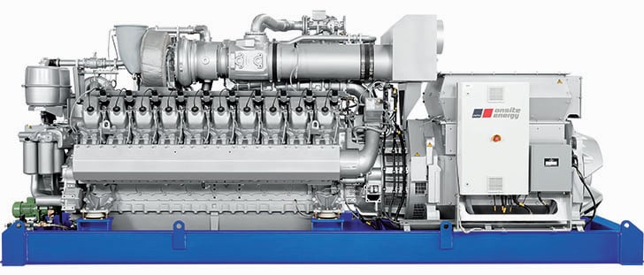
 Generators applicable to high reliability requirements of healthcare and other facilities (on photo: St. Boniface Hospital Emergency Standby Generators; credit: bockstael.com)
Threats of disaster or terror attacks have prompted many facilities to require complete self-sufficiency for continuous operation.
Note that relay protection of a generator is not covered here because this is very complex subject and it has been previously described in several articles (this one for example).
1. Types of Engines
Many generator sets are relatively small in size, typically ranging from several kilowatts to several megawatts. These units are often required to come online and operate quickly. They need to have the capacity to run for an extended period of time.
The internal combustion engine is an excellent choice as the prime mover for the majority of these applications.
Diesel-fueled engines are the most common, but other fuels used include natural gas, digester gas, landfill gas, propane, biodiesel, crude oil, steam and others.
Some campuses and industrial facilities use and produce steam for heating and other processes. These facilities may find it economically feasible to produce electricity as a byproduct of the steam production.
These installations would typically be classified as a cogeneration facility producing a fairly constant power output and operating in parallel with the electric utility system.
2. Types of Generators
Generators can be either asynchronous or synchronous. Asynchronous generators are also referred to as induction generators. The construction is essentially the same as an induction motor. It has a squirrel-cage rotor and wound stator.
An induction generator is a motor driven above its designed synchronous speed thus generating power. It will operate as a motor if it is running below synchronous speed. The induction generator does not have an exciter and must operate in parallel with the utility or another source.
The induction generator requires VARs from an external source for it to generate power. The induction generator operates at a slip frequency so its output frequency is automatically locked in with the utility’s frequency.
An induction generator is a popular choice for use when designing cogeneration systems, where it will operate in parallel with the utility.
In addition, the generator construction offers high reliability and little maintenance. Also, a minimum of protective relays and controls are required. Its major disadvantages are that it requires VARs from the system and it normally cannot operate as a standby/ emergency generator.
Synchronous generators, however, are the most common. Their output is determined by their field and governor controls. Varying the current in the DC field windings controls the voltage output.
The frequency is controlled by the speed of rotation. The torque applied to the generator shaft by the driving engine controls the power output. In this manner, the synchronous generator offers precise control over the power it can generate.
In cogeneration applications, it can be used to improve the power factor of the system.
3. Generator Fundamentals
A generator consists of two primary components, a prime mover and an alternator. The prime mover is the energy source used to turn the rotor of the alternator. It is typically a diesel combustion engine for most emergency or standby systems.
In cogeneration applications, the prime mover may come from a steam driven turbine or other source. On diesel units, a governor and voltage regulator are used to control the speed and power output.
The alternator is typically a synchronous machine driven by the prime mover. A voltage regulator controls its voltage output by adjusting the field. The output of a single generator or multiple paralleled generator sets is controlled by these two inputs.
The alternator is designed to operate at a specified speed for the required output frequency, typically 60 or 50 Hz. The voltage regulator and engine governor along with other systems define the generator’s response to dynamic load changes and motor starting characteristics.
Typical synchronous generators for industrial and commercial power systems range in size from 100–3000 kVA and from 208 V–13,800 V. Other ratings are available and these discussions are applicable to those ratings as well.
Generators must be considered in the short-circuit and coordination study as they may greatly impact the rating of the electrical distribution system.
This is especially common on large installations with multiple generators and systems that parallel with the utility source. Short-circuit current contribution from a generator typically ranges from 8 to 12 times full load amperes.
The application of generators adds special protection requirements to the system. The size, voltage class, importance and dollar investment will influence the protection scheme associated with the generator(s). The mode of operation will influence the utility company’s interface protection requirements.
Paralleling with the electric utility is the most complicated of the utility inter-tie requirements. IEEE ANSI 1547 provides recommended practices.
4. Generator Systems
4.1 Emergency Standby Generator System
There are primarily three types of generator systems. The first and simplest type is a single generator that operates independently from the electric utility power grid. This is typically referred to as an emergency standby generator system.
Figure 3 shows a single standby generator, utility source and a transfer switch. In this case, the load is either supplied from the utility or the generator. The generator and the utility are never continuously connected together.
It should be noted that this type of generator system improves overall electrical reliability but does not provide the redundancy that some facilities require if the generator fails to start or is out for maintenance.

4.2 Multiple Isolated Standby Generators
The second type of generator system is a multiple isolated set of standby generators. Figure 4 shows multiple generators connected to a paralleling bus feeding multiple transfer switches. The utility is the normal source for the transfer switches.
The generators and the utility are never continuously connected together in this scheme.
Multiple generators may be required to meet the load requirements (N system). Generators may be applied in an N+1 or a 2N system for improved system reliability.
In an N system, where N is the number of generators required to carry the load. If a generator fails or is out for maintenance, then the load may be dropped. This is unacceptable for most critical 24/7 operations.
In an N + 1 system, N is the number of generators needed to carry the load and 1 is an extra generator for redundancy. If one generator fails to start or is out for maintenance, it will not affect the load.
Multiple generator systems have a more complex control and protection requirement as the units have to be synchronized and paralleled together. The generators are required to share the load proportionally without swings or prolonged hunting in voltage or frequency for load sharing.
They may also require multiple levels of load shedding and/or load restoration schemes to match generation capacity.
4.3 Multiple Generators Operating in Parallel with Utility System
The third type of system is either one with a single or multiple generators that operate in parallel with the utility system. Figure 5 shows two generators and a utility source feeding a switchgear lineup feeding multiple loads.
This system typically requires generator capacity sufficient to carry the entire load or sophisticated load shedding schemes. This system will require a complete and complex protection and control scheme. The electric utility may have very stringent and costly protection requirements for the system.
IEEE standard 1547 describes the interconnection requirements for paralleling to the utility.
5. Generator Grounding and Bonding
Generator grounding methods need to be considered and may affect the distribution equipment and ratings. Generators may be connected in delta
or wye, with wye being the most typical connection.
A wye-connected generator can be solidly grounded, low impedance grounded, high impedance grounded or ungrounded.
A solidly grounded generator may have a lower zero sequence impedance than its positive sequence impedance. In this case, the equipment will need to be rated for the larger available ground fault current.
An IEEE working group has studied the practice of low resistance grounding of medium-voltage generators within the general industry. This “working group” found that, for internal generator ground faults, the vast majority of the damage is done after the generator breaker is tripped offline, and the field and turbine are tripped.
This is due to the stored energy in the generator flux that takes several seconds to dissipate after the generator is tripped offline.
It is during this time that the low resistance ground allows significant amounts of fault current to flow into the ground fault. Because the large fault currents can damage the generator’s winding, application of an alternate protection method is desirable during this time period.
One of the solutions set forth by this “working group” is a hybrid high resistance grounding (HHRG) scheme as shown in Figure 6.

In the HHRG scheme, the low resistance ground (LRG) is quickly tripped offline when the generator protection senses the ground fault.
The LRG is cleared at the same time that the generator breaker clears, leaving the high resistance ground portion connected to control the transient overvoltages during the coast-down phase of the generator, thereby all but eliminating generator damage.
6. Generator Controls
The engine generator set has controls to maintain the output frequency (speed) and voltage. These controls consist of a governor and voltage regulator. As loads change on the system, the frequency and voltage will change. The speed control will then adjust the governor to correct for the load (kW) change.
The voltage regulator will change the field current to adjust the voltage to the desired voltage value.
These systems often have a load shed scheme, which adds to the complexity.
Multiple generator schemes need a master controller to prevent units from being connected out-of-phase. The sequence of operation is to send a start signal to all generators simultaneously. The first unit up to frequency and voltage will be permitted to close its respective breaker and energize the paralleling bus.
During this time, the breakers for the other generators are held open and not permitted to close until certain conditions are met. Once the paralleling bus is energized, the remaining generators must be synchronized to it before the generators can be paralleled.
Synchronization compares the voltage phasor’s angle and magnitude. Both generators must be operating at the same frequency and phase-matched within typically 5 to 10 degrees with each other.
The voltage magnitude typically must be within 20 to 24%.
If it is running faster, then it will rotate in the clockwise direction.
The greater the frequency difference, the faster is the rotation. It is important that the generators are in phase before they are paralleled. Severe damage will occur if generators are paralleled out-of-phase.
Sources: Power system design basics – Eaton


Very useful information
Great Article.
Very informative. Thanks