
Estimated Study Time: 35 minutes
Gas-insulated substation (GIS)
A gas-insulated substation (GIS) is usually utilized in high voltage applications in which all conductive parts are encapsulated in sealed cylinders with SF6 as the insulating medium. The air-insulated substation (AIS), on the other hand, has air as an insulating medium, and this substation type is almost always an outdoor type.
 Mastering GIS control circuits – AC/DC auxiliary circuits and circuit breaker closing circuit
Historically, GIS was established in Japan in the ’60s due to the urgent need for small footprint substations. Therefore, GIS is not always feasible if space availability is not an issue. The GIS enclosure is designed to accommodate three-phase equipment normally up to 170 kV level and a single-phase equipment beyond that.
GIS is the same as air-insulated substation (AIS) in terms of functionality, but they differ in many other ways. The substation components’ specifications, mounting, and otherwise.
- High Voltage GIS Control Circuits
- GIS Components
- GIS Single-Line Diagram
- Keys for Drawing Reading
- Substation Control Systems
- Download Attachment (PDF) 🔗 ‘Implementation of IEC 61850 based Substation Automation System in Existing 132kV Substation’
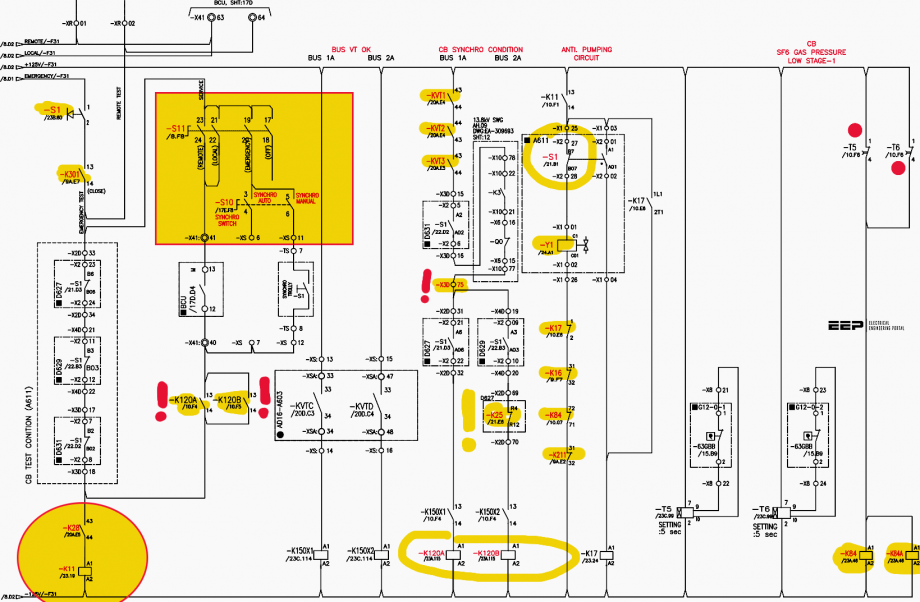
1. High Voltage GIS Control Circuits
SF6 circuit breaker, for example, is used in both AIS and GIS with only one difference which is that the breaker in the GIS has no SF6-to-air bushing. It is directly connected to the GIS module. In the same manner, all components experience such changes to fit in the GIS.
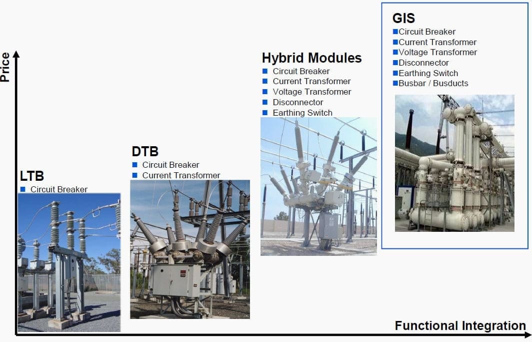
There are several variations to the GIS module ranging from enclosing breaker only to integrating all the components as shown in Figure 1 below.
Although the LCC is not considered as a GIS component, it controls its operation. The LCC is the control cabinet that has the GIS control circuits. These control circuits are similar to what has been discussed in the MV switchgear control circuits two articles:
- Mastering switchgear control circuits: AC/DC circuits & circuit breaker closing circuit
- Mastering switchgear control circuits: trip, BCPU & alarm, indication & interlock circuits.
Figure 1 – GIS Modules
The same principles explained already still apply to these circuits. The exception is that there are additional functions to account for the GIS system size and associated hazards. Thus, it is highly recommended to go through these two articles before proceeding to the GIS control circuits since the basic principles are the same and they are not discussed elaborately here as in the two mentioned articles.
Moreover, some tips to read drawings in general and GIS, in particular, are provided. Many concepts explained in the MV switchgear are not elaborated here, so one needs to go back to these articles if needed.
2. GIS Components
GIS components are encapsulated within SF6 gas, and they are similar to all switchgear types as in Figure 2. However, some specific differences are as follows:
- Circuit breaker: Single-phase breakers designed for the single-pole auto-reclosing mechanism
- Disconnect switch: used to isolated circuit breaker since rack-in/rack-out is not possible in such large breakers (a breaker is a fixed type)
- Grounding switch: safely ground equipment
- Surge arrestor: protects equipment from overvoltage transients caused by external lightning or internal switching events
- Instrument transformers: Current and voltage transformers are of single-phase type inductive type that has one core or more for protection and measurement
- Auxiliary relays: Relays assisting another relay or device in performing an action
- Miniature circuit breakers: breakers used in control circuits
- SF6 gas: Colorless, odorless, non-flammable, inert gas that is 5 times heavier than air and over 100 times better arc quenching than air
- Termination module: Connects switchgear bay to cables, overhead lines, and transformers
- Busbar module: Adjacent bays are connected through expansion joints to absorb constructional tolerance and temperature movements
- Annunciator: Sets alarm signals (light and sound) in case of any problems in the GIS
Figure 2 – GIS Components
3. GIS Single-Line Diagram
The GIS single-line diagram (SLD) is similar to the MV switchgear with richer details. The example in Figure 3 is a double-busbar with single breaker switchgear that encloses main components, like circuit breakers, ground switches, disconnectors, etc. Again, drawing legends are the reference for symbol interpretations.
This GIS nominal voltage level is 145 kV.
A new component that is not found in MV switchgear is the so-called three-position switch (e.g. Q51 − Q1). It has three positions: a closed disconnector, a closed ground switch, a neutral (i.e. both switches open). More of this switch is discussed in control circuits. The disconnectors precede and follow breakers to safely isolate them. This is attributed to the fact that was pointed before, GIS breakers can neither be racked-in nor racked-out.
A closer look at the transformer feeder indicates many GIS components: disconnector, grounding switch, breaker, three-position switch, PT, CT.
Furthermore, the bus coupler links two different busbars as seen above, but another reliability measure is employed in this configuration; the bus section. Breaker (Q0−2) is an example of the bus section that connects two different sections of the very same bus as illustrated in Figure 3.
Figure 3 – GIS single line diagram: Double-Busbar
The bus coupler interconnects the buses vertically while the bus section links the buses horizontally. A simple case considered here is when an operator wants to shift the transformer feeder load from bus-1 to bus-2. The operator must close the near bus coupler and then close the bus-2 disconnector. After that, the bus-1 disconnector should be opened to complete this load transfer maneuver.
Alternatively, the two buses’ voltage could be equalized by closing the bus section breaker (Q0−2) and the far bus coupler (Q0−4). The outcome is the same.
The disconnector and the ground switch closing/opening time is between 1.5-3 seconds, whereas it is about 100 milliseconds for the high-speed ground switch. Seemingly, the sequence of operation for different events is quite complex and this indicates complicated interlocking schemes as we will see in this article and the next one.
4. Keys for Drawing Reading
Drawing comprehension is the cornerstone to understand and analyze substation circuits. It is a large topic, but some keywords are addressed here. The following are the main points with which one need to know before proceeding to substation circuits analysis:
- Drawing type: Commissioning, Markup, As-built
- Drawing details: Transformer feeder, plain feeder, capacitor feeder, etc
- Drawing number
- Sheet number
- Sheet details: List of pages, bill of material, etc
- Cross-reference: Rows (A,B,C,…), Columns (1, 2, 3,…)
- Manufacturer data
- End client data
Each substation drawing number is unique and is used as an address to move between different drawings at ease. For example, a feeder cable could be traced easily by the drawing numbers of the two concerned substations.
Also, a drawing package contains an outline panel arrangement, shown in Figure 4, that describes the general LCC layout, including cable entry and mimic diagram. An internal arrangement of the LCC drawing, on the other hand, depicts all internal connection components, such as terminal blocks, test switches, timers, etc.
Figure 4 – Outline Arrangement of LCC

Figure 5 – Internal Arrangement of LCC
An important drawing (see Figure 6) called terminal block and wire specifications present detailed descriptions of terminal blocks, secondary wires, wire ferrule, and external wires between cubicles.
Related electrical guides & articles


Salem Alshahrani
Electrical engineer (BEE & Meng). Specialized in substation design, especially in LV/MV switchgears and transformers. Passionate in power system planning, analysis, and stability studies.Profile: Salem Alshahrani
