
Estimated Study Time: 8 minutes
Good Grounding
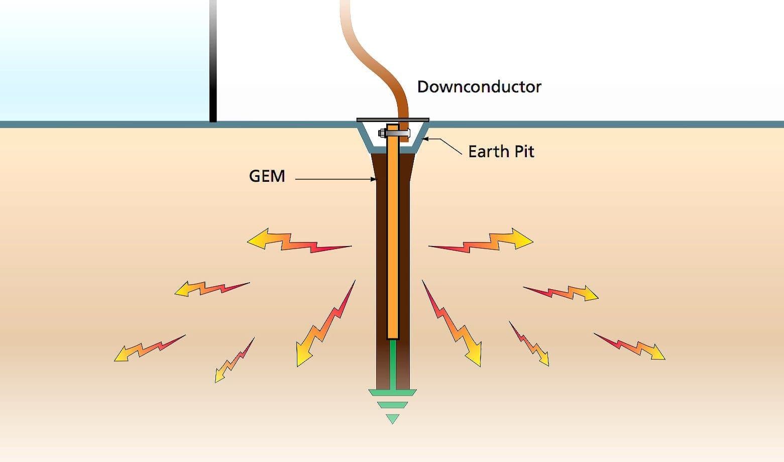
The transient nature of lightning with its associated fast rise times and large magnitude currents mean that special consideration needs to be given to the good grounding, for lightning protection to be effective. Many factors such as soil resistivity variations, installation accessibility, layout and existing physical features are all site specific and tend to affect decisions on grounding methods employed.
 Why is Good Grounding Important And What Can You Do About It? (on photo: groundwire connected to rod with acorn type connector; credit: irm.org)
The primary aim of a direct strike grounding system is to efficiently dissipate lightning energy into the ground and to help protect equipment and personnel.
Grounding Principles
Low impedance is the key to lightning protection. All grounding connections should be as short and direct as possible to minimize inductance and reduce peak voltages induced in the connections.
The ground electrode system must efficiently couple lightning surges into the ground by maximizing capacitive coupling to the soil. The resistance of the ground itself to lightning currents must also be minimized.
Only when all these factors are taken into account will maximum lightning protection be achieved.
Ground Impedance
Soil resistivity is an important design consideration. It varies markedly for different soil types, moisture content and temperatures and gives rise to variations in ground impedances.
Short, Direct Ground Connections
The voltage generated by a lightning discharge depends primarily on the risetime of the current and the impedance (primarily inductance) of the path to ground.
Extremely fast rise times result in significant voltage rises due to any series inductance resulting from long, indirect paths, or sharp bends in the routing of ground conductors. This is why short, direct ground connections are important.
Coupling from the Electrode System to the Ground
The efficiency of a ground electrode system in coupling a lightning current to ground is dependent on a number of factors, including the geometry of the ground electrode system, the shape of the conductors and the effective coupling into the soil.
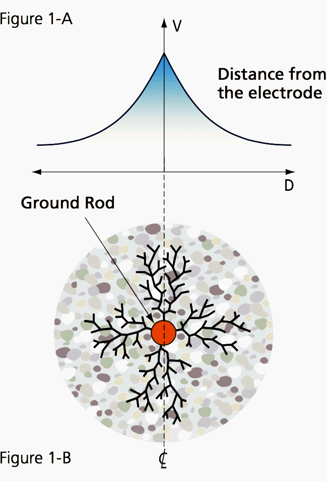
Figure 1-B illustrates current flow from the injection point of a single ground electrode. As current flows out from the central injection point, a voltage gradient on the ground surface around the electrode is produced. This gradient levels off to a plateau at some distance from the electrode, as seen in Figure 1-A.
Characteristics of a Good Grounding System
In short, four characteristics are of essential importance for grounding //
- Good electrical conductivity
- Conductors capable of withstanding available electrical fault currents
- Long life – at least 40 years
- Low ground resistance and impedance
The basic philosophy of any grounding installation should be an attempt to maximize the surface area of electrodes or conductors with the surrounding soil. Not only does this help to lower the earth resistance of the grounding system, but it also greatly improves the impedance of the grounding system under lightning surge conditions.
Equipotential bonding
Equipotential bonding helps ensure that hazardous potential differences do not occur between different incoming conductors such as metallic water services, power systems, telecommunication systems and the local ground, and also minimizes step and touch potentials.
Good corrosion resistance
The ground electrode system should be corrosion resistant, and compatible with other conductors that are buried and bonded to the ground system.
Copper is by far the most common material used for grounding conductors. In general, some form of maintenance or inspection procedure should be adopted to ensure the long-term effectiveness of a grounding system.
Electrically and mechanically robust and reliable
Mechanical coupling can be used to join ground conductors, but suffers from corrosion effects when dissimilar metals are involved.
As well as mechanical strength, CADWELD connections provide excellent low impedance, long life electrical connections with excellent corrosion resistance.
Ground Resistance
When current flows from a ground electrode into the surrounding soil, it is often described as flowing through a series of concentric shells of increasing diameter. Each successive shell has a greater area for current flow and consequently, lower resistance.
At some point distant from the earth conductor the current dissipation becomes so large and current density so small, that the resistance is negligible.
In theory, the ground resistance may be derived from the general formula:
R = P × L/A Resistance = Resistivity × Length/Area
This formula illustrates why the shells of concentric earth decrease in resistance the farther they are from the ground rod:
R = Resistivity of Soil × Thickness of Shell / Area
In the case of ground resistance, uniform earth (or soil) resistivity throughout the volume is assumed, although this is seldom the case in nature. The equations for systems of electrodes are very complex and often expressed only as approximations.
The most commonly used formula for single ground electrode systems, developed by Professor H.R. Dwight of the Massachusetts Institute of Technology, is the following:
R = ρ/2πL
Where:
- R = resistance in ohms of the ground rod to the earth (or soil) L = grounding electrode length
- r = grounding electrode radius
- ρ = average resistivity in ohms-cm.
Conditions Influencing Soil Resistivity
The resistance of the earth itself (soil resistivity) can significantly impact the overall impedance of the grounding system. Several factors, such as soil composition, moisture content, mineral content, contaminants, etc., determine the overall resistivity of the earth.
| SOIL TYPE | Resistivity Ohm/cm | ||
| Average | Min. | Max. | |
| Fills – ashes, cinders, brine wastes | 2,370 | 590 | 7,000 |
| Clay, shale, gumbo, loam | 4,060 | 340 | 16,300 |
| Clay, shale, gumbo, loam with varying proportions of sand and gravel | 15,800 | 1,020 | 135,000 |
| Gravel, sand, stones, with little clay or loam | 94,000 | 59,000 | 458,000 |
Reference // Grounding and Bonding For Electrical Systems by ERICO
Related electrical guides & articles


Edvard Csanyi
Hi, I'm an electrical engineer, programmer and founder of EEP - Electrical Engineering Portal. I worked twelve years at Schneider Electric in the position of technical support for low- and medium-voltage projects and the design of busbar trunking systems.I'm highly specialized in the design of LV/MV switchgear and low-voltage, high-power busbar trunking (<6300A) in substations, commercial buildings and industry facilities. I'm also a professional in AutoCAD programming.
Profile: Edvard Csanyi

Please tell me how to calculate the cross section of the bare copper cable for the Inter-meshed earth-termination system of an industrial plant.
muy interesante articulo me podria enviar una copia
Gracias