
Estimated Study Time: 21 minutes
Earthing For Safety
Provision of adequate grounding in a substation and switching stations are very important for the safety of operating personnel as well a electrical devices do not rise above tolerable thresholds and that the earth connection is rugged to dissipate the fault to the earth.
 What does a good grounding of the power substation and switching station really mean?
The importance of an effective, durable and a dependable earth for ensuring safety from electrical hazards does not require to be elaborated upon more.
By earthing, connecting the electrical equipment to the general mass of the earth, this has a very low resistance.
- Requirements Of a Good Substation Earthing
- Maximum Permissible Resistance Of Earthing System
- Touch Voltage (E-TOUCH)
- Step Voltage (E STEP)
- Earthing System In a Substation
- Location Of Earth Electrode
- Earthing Of Various Equipment In The Substation
- Distribution Transformer Structure Earthing
1. Requirements Of a Good Substation Earthing
The object of an earthing system in a substation is to provide under and around the substation a surface that shall be at a uniform potential and near zero or absolute earth potential as possible.
The primary requirements of a good earthing system in a substation are:
- It stabilizes circuit potentials with respect to ground and limits the overall potential rise.
- It protects life and property from over voltage.
- It provides low impedance path to fault currents to ensure prompt and consistent operation of protective devices during ground faults.
- It keeps the maximum voltage gradient along the surface inside and around the substation within safe limits during ground fault.
2. Maximum Permissible Resistance Of Earthing System
| Large power station | 0.5 ohms |
| Major sub-station | 1.0 ohms |
| Small sub-station | 2.0 ohms |
| In all other cases | 8.0 ohms |
| The earth continuity inside an installation | 1.0 ohms |
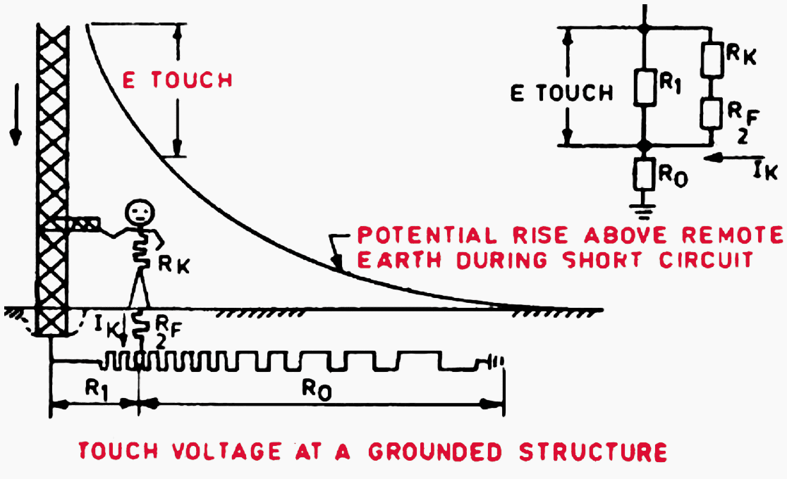
3. Touch Voltage (E-TOUCH)
Definition – The potential difference between a ground metallic structure and a point on the earth’s surface separated by a distance equal to the normal maximum horizontal reach of a person, approximately one meter as shown in figure 1.
4. Step Voltage (E STEP)
Definition – The potential difference between two points on the earth surface separated by distance of one pace that will be assumed to be one meter in the direction of maximum potential gradient as shown in figure.

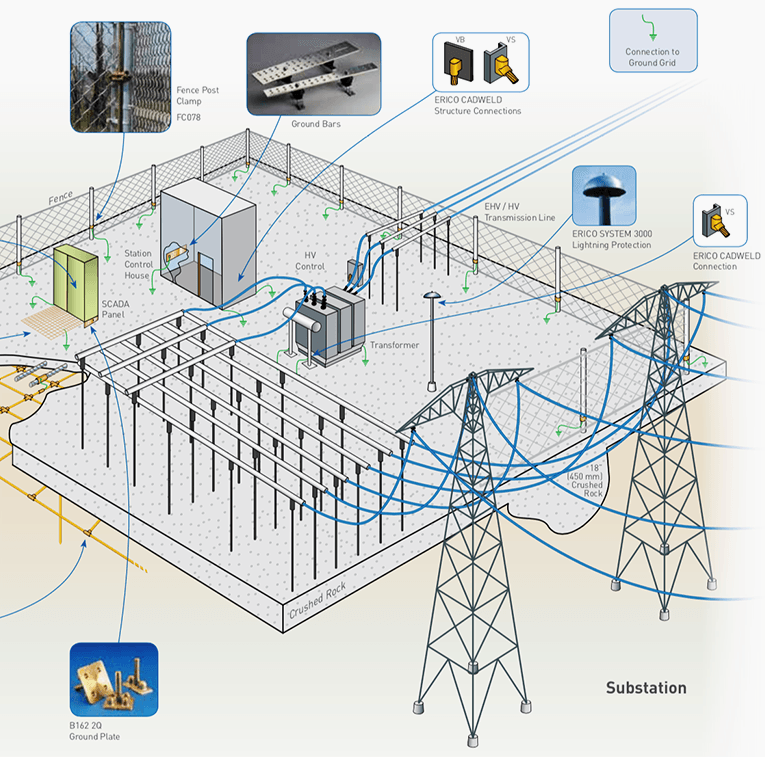
5. Earthing System In a Substation
The earthing system comprises of earthing (or) grid, earthing electrodes, earthing conductors and earth connections.
5.1 Earth Mat or Grid
The primary requirement of earthing is to have a very low earth resistance. If the individual electrodes driven in the soil are measured it will have a fairly high resistance.
But if these individual electrodes area inter linked inside the soil, it increases the area in constant with soil and creates a number or paralleled paths and hence the value of earth resistance in the interlink state, which is called combined earth resistance, will be much lower than the individual resistance.
Hence if a ground electrode is driven in the soil, the interlinking can be done by a small link between that electrode and earth mat running nearby.
The spreading of such a mat in the soil also ensures the object of earthing that and surface under and around the sub-station is kept at as nearly absolute earth potential as possible.
5.2 Construction of Earth Mat
The sub-station site including the fence is segregated at intervals, of say four meters width along with length and breadth wise. Trenches of one meter to 1.5 meter depth and one meter width is dug along these lines. The earthing conductors of sufficient sizes (as per fault current) are placed at the bottom of these trenches. All the crossing and joints are braced.
The trenches are then filled up with soil of uniform fine mass of earth mixed with required chemicals depending upon the soil resistivity. If location of equipment is fixed, the intervals are also arranged that the earth mat passes nearby the equipment location to facilitate for easy interlinking.
Normally the earth mat is buried horizontally at a depth of about half a meter below the surface of the ground and ground rods at suitable points.
5.3 Earth Mat in a Sub-Station
Earth Mat is connected to the Following in a Substation:
- The neutral point of such system through its own independent earth.
- Equipment frame work and other non-current carrying parts of the electrical equipments in the sub-station.
- All extraneous metallic frame work not associated with equipment.
- Handle of the operating pipe.
- Fence if it is within 2 m from earth mat.
6. Location Of Earth Electrode
The location of earth electrode should be chosen in one of the following types of soil in the order of preference:
- Wet marshy ground.
- Clay, loamy soil and arable land
- Clay and loam mixed with varying proportions of sand, gravel and stones.
- Damp and wet sand, peat.
Dry sand, gravel chalk limestone, granite, very stone ground and all locations where virgin rock is very close to the surface should be avoided.

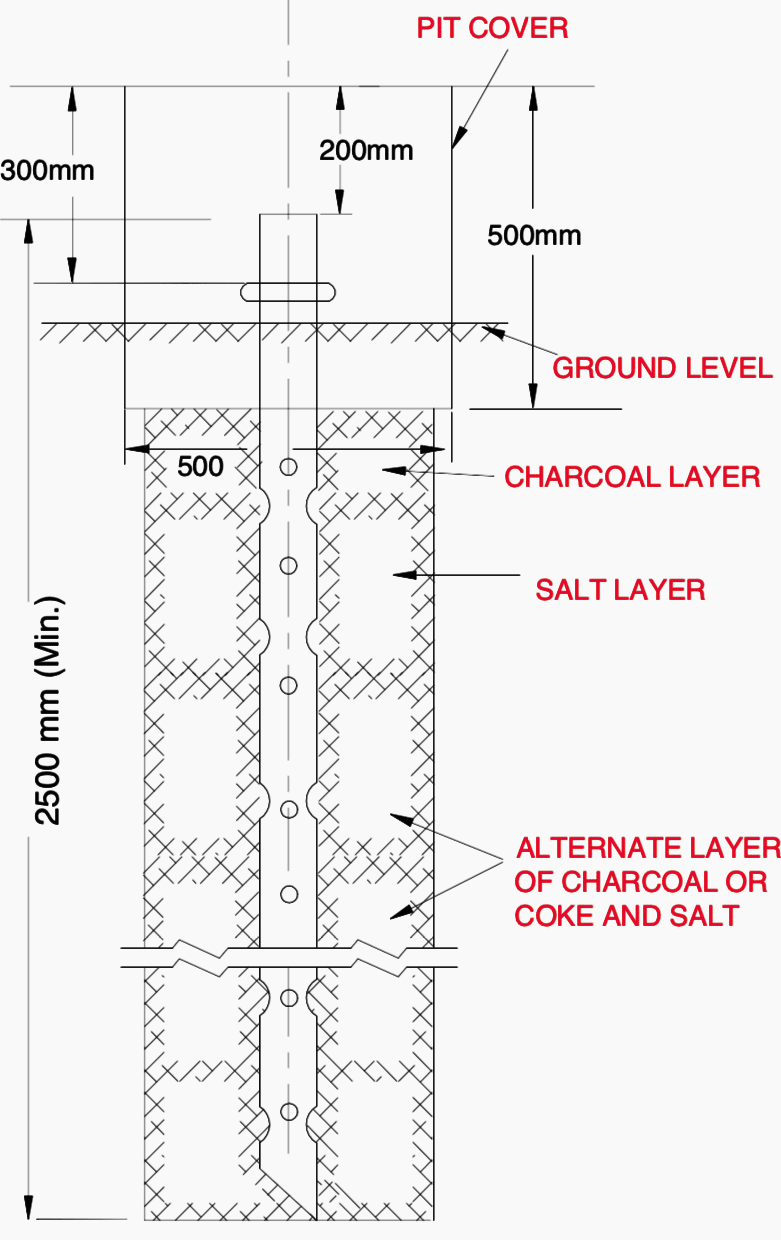
6.1 Pipe Electrode
It should be made of ‘B’ class G.I pipe. The internal diameter should not be smaller than 38 mm and it should be 100 mm fore cast Iron pipe. The length of the pipe electrode should not less than 2.5 m. It should be embedded vertically.
Where hard rock is encountered it can be inclined to vertical. The inclination shall not more than 30 from the vertical.
The distance between two electrodes in such a case shall preferably be not less than twice the length of electrode as shown in figure 5.
7. Earthing Of Various Equipment In The Substation
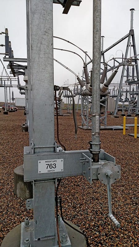
7.1 Isolators and switches
A flexible earth conductor is provided between the handle and earthing conductor attached to the mounting bracket and the handle of switches is connected to earthing mat by means of two separate distinct connections made with MS flat.
One connection is made with the nearest longitudinal conductor, while the other is made to the nearest transverse conductor of the mat.
7.2 Lightning Arresters
Conductors as short and straight as practicable to ensure minimum impedance shall directly connect the bases of the lightning arresters to the earth grid. In addition, there shall be as direct a connection as practicable from the earth side of lightning arresters to the frame of the equipment being protected.
In the case of lighting arresters mounted near transformers, earthing conductor shall be located clear off the tank and coolers in order to avoid possible oil leakage caused by arcing.
7.3 Circuit Breakers
For every breaker there will be five earth connections to the earth mat with: MS flat (i) breaker body (ii) relay panel (iii) CTs of the breaker (iv) Two side of the breaker structure.
7.4 Transformers
The tank of each transformer shall be directly connected to the main grid. In addition there shall be as direct a connection as practicable from the tank to the earth side of projecting lightning arresters.
The earthing of neutral bushing shall be by two separate strips to the earth grid and shall likewise be run clear to rank cell and coolers.

7.5 Current Transformers and Potential Transformers
The supporting structures of Current Transformer and Potential Transformer unit of bases, all bolted cover plates to which the bushings are attached connected to the earthing mat by means of two separate distinct connections made with MS flat.
One connection is made with the nearest longitudinal conductor, while the other is made to the nearest transverse conductor of the mat.

7.6 Other Equipment
All equipment’s, structures, and metallic frames of switches and isolators shall be earthed separately as shown in figure 11.

7.7 Fences
The Sub-station fence should be generally too far outside the substation equipment and grounded separately from the station ground. The station and the fence ground should not be linked.
If the distance between the fence and station structures, cannot be increased at least five feet and if the fence is too near the substation equipment structure etc., the station fence should be connected to the fence ground.
Otherwise a person touching the fence and the station ground simultaneously would be subjected to a very high potential under fault conditions.
In a fence very near to the station area, high shock voltage can be avoided by ensuring good contact between the fence stations and by grounding the fence at intervals. The station fence should not be connected to the station ground but should be grounded separately.
If however, the fence is close to the metal parts of substation, it should be connected to the station ground.
7.8 Ground Wire
All ground wires over a station must be connected to the station earth grid.
In order that the station earth potentials during fault conditions are not applied to transmission line ground wires and towers, all ground wires coming to the station must be broken at and insulated on the station side of the first tower or pole external to the station by means of 10” disc insulator.
7.9 Cables and Supports
Metal sheathed cables within the station earth grid area must be connected to that grid. Multi-core cables must be connected to the grid at least at one point. Single core cables normally should be connected to the grid at one point only.
7.10 Panels and Cubicles
Each panel or cubicle should be provided near the base with a frame earth bar of copper to which shall be connected the metal bases and covers of switches and contactor unit.
The frame earth bar shall in turn be connected to the earth grid by an earthing conductor.

8. Distribution Transformer Structure Earthing
Let’s see the following nine rules you should follow for correct grounding of distribution transformer structure:
- For earthing three earth pits in triangular formation at a distance of six meter from each other are to be provided.
- Earth pit should be digged for 45 cm x 45 cm size and 5 ft. depth.
- 3 Nos. of 40 mm dia and 2.9 mm thickness and 3 mts. (10 ft) length of earth pipe should be used for earthing.This earth pipe is erected in 5 ft. depth earth pit and for the balance length of earth pipe is driven by hammering into the ground.
- When a pipe is driven into the earth, the earth surrounding the pipe can be considered to be consisting of concentric cylinders of earth which will be bigger in size and area, as they are away from the pipe. The current can travel into the earth with large area having little resistance.
- 3 m. length of electrode will have contact with the earth area of 3 m in radius. Hence to have better effect 3 m pipe should be fixed at a distance of 6 m (i.e.) twice the distance of pipe length.
- For better earth connection, one G I clamp should be welded to the earth pipe and the other clamp bolted with 2 nos. 11/2 x 1⁄2 G I bolt nuts and 4 nos. G. I. washers to the earth pipe.
- Two separate distinct connections through G I wire should be made from the transformer neutral bushing to the earth pit No. 2.
- Two separate distinct connections through GI wire should be made from the transformer HT lightning Arrester to the earth pit No. 1.As far as possible this earth wire should not have contact with other earth wire connections. If needed PVC sleeves can be used for insulation.
- Two separate distinct connections through GI wire from the following parts of the structure should be made to the earth pit No. 3 as shown in figure 14 below.
- Metal part of the disc and stay.
- Top channel.
- AB switch frame, metal part of the insulator, side Arms.
- HG fuses frame and metal part of the insulator.
- LT cross arm, metal part of the insulator, open type fuse frame.
- AB switch guide and operating pipe ( At the top and bottom )
- Transformer body.
- Belting angle.
- Seating channel
- LT lightning arrester.
The above earth connections should be made as far as possible without joints. Wherever joints are necessary, GI sleeves should be used by proper crimping.
The earth pits No. 2 and 3 can be interlinked to serve as parallel path and lower the earth resistance.
If the earth resistance of the earth pit No. 1 is high, then another earth pit No. 4 can be formed as a counter poise earth and linked with the HT lightning arrester pit.

Reference // Handbook on maintenance of electrical general services substation by Government of India / Ministry of railways
Related electrical guides & articles


Edvard Csanyi
Hi, I'm an electrical engineer, programmer and founder of EEP - Electrical Engineering Portal. I worked twelve years at Schneider Electric in the position of technical support for low- and medium-voltage projects and the design of busbar trunking systems.I'm highly specialized in the design of LV/MV switchgear and low-voltage, high-power busbar trunking (<6300A) in substations, commercial buildings and industry facilities. I'm also a professional in AutoCAD programming.
Profile: Edvard Csanyi

best website for all engineers
Very good article 👍
Thank you so much for the substation grounding information really helped me on my studies. What are different types of controlling the potential earthing systems?
Real thank you engineers for the good knowledge shared here. I love electrical engineering and am an electrical technician who loves learning new ideas Everytime.
Difference power station of 8resistance and their values. Please can I get the answer to the above question
What is the Standard for above permissible earth resistance ?
Great article.
Great article, keep it up
Question -: Why Transformer (supply) neutral connection via individual Treated Earth Pit & why it is not linked with Grid earthing.
Very useful article for our ongoing project of a new ASU plant.
The Earthing System of the installations,one of the most confusion issues, is guided well by EEP .Thanks for that.
This article is a mind opener to Substation works (Electrical).
Maybe I overlooked it but my question is which material shall be used for the earth mat, copper, steel, ???
Very informative and straight forward..
Excelente información. Esta muy claro todos los conceptos expuestos. Mil Gracias desde Colombia.
Brilliant article…very informative
Very good article.Is there any provision for training on Electrical protection system and how to study electrical engineering drawing ?
Nice article.
However, I would like to know about the standard that recommend Maximum Permissible Resistance value of Earthing System that you mentioned in content #2.
Excellent
Great and very useful information.
Really useful summary for electrical consultant! Thanks.
Quite useful article for the electrical engineers and those associated with the field work.
Nice Article and valued informations
Great article. It’s good to have all the earthing design aspects in a brief document. A small comment on paragraph 5.1: “area inter linked inside the soil, it increases the area in constant with soil”, I think it should be “are inter linked inside the soil, it increases the area in contact with soil”.
Greetings.
Good article. I think the burial depth needing to be greater than the frost depth is a critical design factor. There are studies in cold weather that shoes a dramatic increase in resistivity during winter months. I’ve confirmed this affect with informal studies.