
Estimated Study Time: 6 minutes
The Grounding system that works
The performance of the grounding system is determined by the quality of the following five components all of which are of equal importance.
 What makes a good grounding system? (photo credit: irm.org)
- The grounding electrode conductor
- The grounding connections
- The grounding electrode
- Electrode to soil resistance
- The soil
1. The grounding electrode conductor
Typically made from copper or copper-bonded steel, the grounding electrode conductor must be large enough to withstand the maximum available fault current over the maximum clearing time.
2. The grounding connections
Often overlooked, the grounding connections are used to tie the elements of the electrode system together. Exothermically welded connections provide a molecular bond that will never loosen or corrode. Mechanical connectors, such as crimp, bolted, and wedge type, rely on physical point- to-point surface contact to maintain the integrity of the electrical connection.
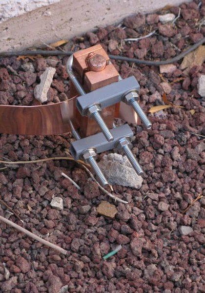
IEEE® Standard 837 (Standard for qualifying permanent substation grounding connections) provides detailed information on the application and testing of permanent grounding connections.
3. The grounding electrode
The grounding electrode provides the physical connection to the earth and is the instrument used to dissipate current into it. There are two main types of electrodes //
‘Natural’ electrodes are intrinsic to the facility and include metal underground water pipe, the metal frame of the building (if effectively grounded), and reinforcing bar in concrete foundations.
‘Made’ electrodes are installed specifically to improve the performance of the ground system and include wire meshes, metallic plates, buried copper conductor and rods or pipes driven into the ground. The ground rod is the most widely used electrode.
4. Electrode to soil resistance
Amount of rod surface and rod replacement are the controlling factors. Doubling diameter reduces resistance by only 10% and is not cost effective.
5. The soil
The soil resistivity, measured in ohm-centimeters or ohm-meters, plays a significant role in determining the overall performance of the grounding system and must be known before a proper grounding system can be engineered.
Measuring soil resistivity allows the design engineer to locate an area with the most conductive soil and to determine the depth of the conductive soil so that electrodes can be placed accordingly.
The grounding system will carry little or no current for long periods of time until a fault occurs or a lightning strike or other transient requires dissipation. At that point, the grounding system components will be expected to perform like new while conducting large amounts of current.
Most of the grounding system is concealed below grade, making inspection of the grounding components difficult or impossible. The underground environment is a harsh one. The initial selection of the components used in the grounding system is of critical importance to its long-term effectiveness.
Grounding Systems (VIDEO)
Difference between ‘Natural’ and ‘Made’ electrodes
The ground electrode is a critical component of the grounding system. Many different types of electrodes are available, some “natural” and some “made”. The natural types include metal underground water pipe, the metal frame of a building (if effectively grounded), a copper wire or reinforcing bar in a concrete foundation or underground structures or systems.
Consideration should be given to bonding of natural earths to ensure electrical continuity with a facility’s other “earths”.
“Made” electrodes are specifically installed to improve the system grounding or earthing. These earth electrodes must ideally penetrate into the moisture level below the ground level to reduce resistance. They must also consist of metal conductors (or a combination of metal conductor types), which do not corrode excessively for the period of time they are expected to serve.
Made electrodes include rods or pipes driven into the earth, metallic plates buried in the earth or a copper wire ring encircling the structure.
To conclude //
Grounding systems are VERY important. It is not expensive to build an appropriate ground system during initial construction of a facility, but it can be very expensive to add to it, enhance it, or replace it after the facility is complete.
Care should be taken to design a system that is appropriate both for clearing ground faults and dissipating lightning energy.
Reference // Grounding and Bonding For Electrical Systems by ERICO
Related electrical guides & articles


Edvard Csanyi
Hi, I'm an electrical engineer, programmer and founder of EEP - Electrical Engineering Portal. I worked twelve years at Schneider Electric in the position of technical support for low- and medium-voltage projects and the design of busbar trunking systems.I'm highly specialized in the design of LV/MV switchgear and low-voltage, high-power busbar trunking (<6300A) in substations, commercial buildings and industry facilities. I'm also a professional in AutoCAD programming.
Profile: Edvard Csanyi

Is very helpful, thanks so much. For my part they are very helpful and I always translate them into the mother tongue and educate others.
Is very helpful, thanks so much. God blessed
Thank you, Mohamed.
Thanks,🙏 and i want to know the good exactly value of the soil resistivity.
Thank you so much for publishing a good technological method to make a healthy earth grounding.
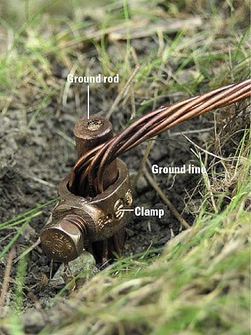
The photo with the caption “Grounding Electrode (ground rod) – photo credit: diyadvice.com” hads the grounding conductor under the bolt instead of on the other side of the rod, clamped between the rod and the clamp.
Thank you very much for your explains.
It is proposed copper brazing (welding) between ground rod and ground line before clamping since ground line is shown multiple stand copper wire to avoid oxidization (layer) between ground rod ground line,clamp
ELECTRICAL ENGINEER @ (GIACL LTD.)
Above information is very useful can you send size of conductor & depth of earthing for different current rating.
thank you
This is ver helpful. Please publish Full technical articles about Grounding and also Bonding. Thank you.