
Estimated Study Time: 20 minutes
Operation of LV/MV Switchgear
The purpose of this guideline is to provide suggested practices for the operation and inspection of medium voltage (2 to 13.8 kV) and low voltage (200 to 480 volt) draw-out switchgear circuit breakers and contactors. Good operating practices are critical to obtain the best service and performance from plant equipment and to ensure a safe environment for plant personnel.
 Good operating practices for switchgear circuit breakers and contactors
The article describes the responsibility of operating personnel and their daily checks and inspections of switchgear. We’ll also describe the best practices for operating and protecting transformers, motors, buses, cables, circuit breakers, and contactors.
We’ll discuss the load feeder overcurrent and ground fault protection practices, as well as the source and tie overcurrent protection and other important practices regarding transformers.
We’ll touch the switchgear bus transfers, and discuss the issues ocurring during paralleling two sources and switch time transfer schemes.
- Operator Inspections
- Protection:
- Switchgear Bus Transfers:
- Attachment (PDF) 🔗 Download ‘Secondary System Protection Performance Study with IEC 61850 Process Bus Architecture’
1. Operator Inspections
It is the responsibility of operating personnel to establish and maintain scheduled routine inspections of all plant switchgear. Circuit breakers, contactors, and buses must be maintained clean and dry to reduce the possibility of insulation failures that can result in explosions and fire. In general, an inspection frequency of once per day is recommended.
The following daily checks and inspections of switchgear locations are recommended:
- Dropped or actuated protective relay targets. Targets found should be reset and recorded in the control room log book.
- Audible noise from electrical arcing.
- Unusual smell from overheated or burning insulation.
- Moisture intrusion, for example, roof leaks, water on the floor.
- Status lamps and semaphores are working properly.
- Pressurizing room fans and dampers are functioning properly to mitigate moisture intrusion and other contamination.
- Switchgear room doors closed properly to mitigate contamination.
- Switchgear cubicle doors are closed to mitigate contamination.
- Panels for accessing breaker racking mechanisms, cable terminations, and other purposes are closed to mitigate contamination.
- Breakers and contactors are kept in their respective cubicles or in special enclosures (usually equipped with heaters) designed to keep the equipment clean and dry.
- Switchgear room lighting is functioning properly.
- Cubicle labeling is consistent with plant policy and accurately describes the source, tie, and feeder positions.
- Rack-in tools and protective safety gear are stored and maintained properly.
- Housekeeping is performed often enough to keep the room clean and orderly.
Maintenance orders should be prepared for any anomalies found during the foregoing inspection process.
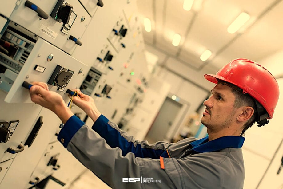
Figure 1 – Testing of low-voltage withdrawable air circuit breaker cubicle

2. Protection
Protective relays are coordinated in a way that only those circuit breakers or contactors that need to be operated to isolate faults are automatically tripped open. This allows the maximum amount of equipment to remain in-service and reduces the impact to on-line generating units. It also provides an indication as to the location of the electrical fault.
Electrical faults in transformers, motors, buses, cables, circuit breakers, and contactors are permanent in nature, and protective relay operations must be thoroughly investigated before re-energizing the equipment.
Electrical short circuits are usually in the range of 15,000 to 45,000 amps depending on the size and impedance of the source transformer.
Consequently, these relays do not always provide ideal thermal overload protection, and operations must rely on transformer temperature alarms, ammeters, or DCS alarms for that purpose.
Accordingly, the overcurrent tripping of a source or tie circuit breaker usually indicates a short circuit and not an overload condition.
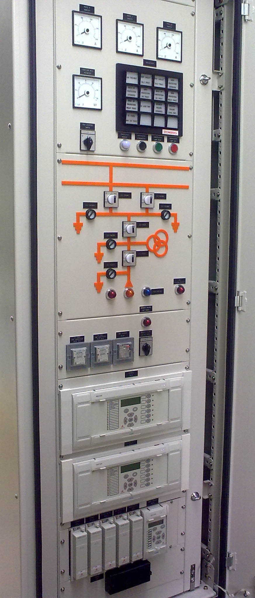
Figure 2 – Control and protection panel with MICOM relays
2.1 Load Feeder Overcurrent Protection
Load feeders are equipped with fast-acting instantaneous overcurrent elements (fuses for contactors) that will clear short circuits in the cables or load (motors or transformers) by isolating the faulted circuits before source and tie breaker overcurrent relays can operate.
Further Study – The essentials of overcurrent protection
The essentials of overcurrent protection you are not allowed to forget (types and principles)
2.2 Load Feeder Ground Protection
Designs that limit the ground fault current (usually around 1000 amps) apply separate ground relays that will actuate for ground faults only. These relays trip with very short time delays to isolate the grounded feeders before source or tie circuit breaker ground relays can operate.
Further Study – Why Ground Fault Protection Matters and Which Scheme For Sensing Ground Faults To Choose
Why Ground Fault Protection Matters and Which Scheme For Sensing Ground Faults To Choose
2.3 Source and Tie Overcurrent Protection
Source and tie breakers are not equipped with instantaneous tripping elements. They rely on time delay to achieve fault coordination with downstream buses and loads.
Typically, these relays are timed at maximum three-phase short circuit current levels and are set to operate in 0.4 to 0.8 seconds.
Normally, the relays have an inverse time characteristic, and lower current levels will increase the time delay for all relays correspondingly. Typically, the tie breaker to another bus will be set to operate in around 0.4 seconds and the source transformer low side breaker in around 0.8 seconds.
They also provide backup protection if a feeder breaker fails to clear a faulted cable or load.
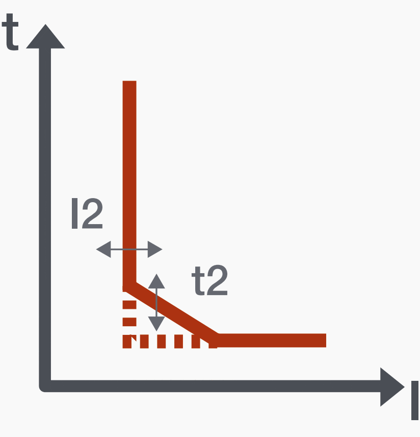
Figure 3 – Time-delayed overcurrent (S – ANSI 51 & 50TD)
2.4 High Side Source Transformer Overcurrent Protection
The source transformer high side overcurrent relays are normally set to operate for maximum three-phase short circuits on the low voltage side in around 1.2 seconds. This provides enough time delay to coordinate with low voltage or secondary side overcurrent relays.
The relays usually have an inverse time characteristic, and lower current levels will increase the time correspondingly. The source transformer high side overcurrent relays assume that the fault is in the transformer, low voltage side connecting buses or cables, or in the low voltage circuit breaker and will trip all equipment necessary to isolate the fault.
In the case of UATs, which are usually equipped with differential protection, the high side overcurrent relays will also provide a complete electrical trip of the unit and main step-up transformer. The high side overcurrent relays also provide stuck breaker protection if the low side breaker fails to interrupt a fault.
Suggested Study – Power System Relaying For Final Year Undergraduate Students and Professionals
Power System Relaying For Final Year Undergraduate Students and Professionals
2.5 Source and Tie Residual Ground Protection
Designs that limit the ground fault current (usually around 1000 amps) apply separate ground relays that will actuate for ground faults only. Source and tie breaker ground relays are not equipped with instantaneous tripping elements. They rely on time delay to achieve fault coordination with downstream buses and loads. Typically, these relays are timed at maximum ground fault current levels and are set to operate in 0.7 to 1.1 seconds.
Normally, the relays have an inverse time characteristic, and lower current levels will increase the time delay for all relays correspondingly. Typically, the tie breaker to another bus will be set to operate for 100% ground faults in around 0.7 seconds and the source transformer low side breaker in around 1.1 second.
They also provide backup protection if a feeder breaker fails to clear a grounded cable or load.
Further Study – Resistance grounding booklet: Questions and answers with industry experts
Resistance grounding booklet: Questions and answers with industry experts
2.6 Source Transformer Neutral Ground Protection
Designs that limit the ground fault current (usually around 1000 amps) apply separate ground relays that sense the ground current flowing in the transformer neutral. Only ground faults will actuate these relays. The source transformer neutral ground relay is normally set to operate for maximum ground faults in around 1.5 seconds.
This provides enough time delay to coordinate with the source and tie breaker ground relays.
The neutral ground relay is designed to isolate ground faults on the low voltage or secondary side of the source transformer. This includes the transformer low voltage winding, low voltage circuit breaker, and connecting buses or cables. The neutral ground relay will also back up the low side breaker if it fails to clear a ground fault condition.
Watch the Video – Definite Time and Inverse Time Overcurrent Protection
2.7 Alarm-Only Ground Schemes
Alarm-only ground schemes limit the ground fault current to just a few amps. Typical values are 1.1 amps for 480 volt systems and 3.4 amps for 4 kV systems. On wye connected source transformers, the neutral is normally grounded through a grounding transformer. On delta connected source transformers, the ground current is usually supplied by three transformers connected grounded wye on the primary and broken delta on the secondary.
In both cases, voltage relays are applied on the secondary sides of the grounding transformers to alarm for ground conditions. In the later scheme, blown primary fuses to the ground detector transformers can cause an alarm condition.
Both relay schemes provide alarms (typically 10% and higher) for all grounded apparatus on the particular electrical system, including the source transformer low voltage or secondary windings, and all connected buses, cables, breakers, potential transformers, and loads.
When one phase of a three-phase system has a 100% ground, the voltage to ground on the other two phases almost doubles (1.73 times higher). This means that the electrical insulation for all equipment on the system has to withstand a much higher voltage to ground when one of the other phases is grounded. This voltage is normally above the continuous insulation rating of installed cables and other electrical apparatus.
Consequently, plant operators are expected to isolate and clear ground faults within a relatively short time period. If the ground fault is not cleared in a timely manner, it may develop into a high current short circuit condition if another phase fails to ground from the higher operating voltage to ground.
Because short circuits often result in explosions, fire, and loss of generation, it is in the interest of operations to have a predeveloped plan for quickly isolating grounds. This usually involves switching off nonessential loads, transferring to a different source transformer, and reducing generation to a point where other loads can be taken out of service.
Related Reading – 6 alarms coming from a substation transformer you MUST take very seriously
6 alarms coming from a substation transformer you MUST take very seriously
3. Switchgear Bus Transfers
3.1 Paralleling Two Sources
Paralleling two different sources is the preferred method of transferring from one source to another. This method is not stressful to motors, is bumpless, and does not jeopardize a running unit. However, in many designs, the amount of short circuit current available during the parallel exceeds the interrupting capability of feeder breakers.
Source and tie breakers will not be affected, but feeder breakers may not be able to clear close in faults and the breakers may be destroyed in the process. Consequently, the duration of parallel should be kept to a minimum (a few seconds) to reduce the exposure time and likelihood of a feeder fault occurring.
Typically, this is more of a problem when the generating unit feeds one system and the reserve, or startup transformer is fed from a different system. Reducing generation will normally bring the phase angles closer together as the generator’s power angle reduces from the lower load.
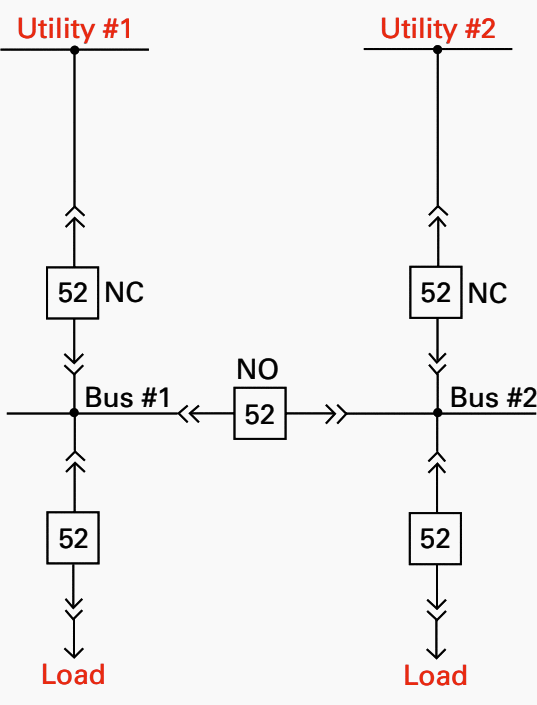
Figure 4 – Two-Source Utility with Tie Breaker
3.2 Drop Pickup Transfers
Drop pickup or switch time transfer schemes are potentially damaging to motors and may cause the loss of a running unit or interruption of an operating process if the new source breaker fails to close after the prior source breaker trips open. When a bus is de-energized, the connected motors act like generators and provide a residual voltage to the bus.
This voltage usually collapses in approximately 1 second.
However, drop pickup transfers are much faster than 1 second, and the residual voltage can add to the new source voltage. If the vector sum of the two voltages exceeds 133% of motor rated voltage, the transfer can reduce the operational life of the motors involved.
3.3 Automatic Bus Transfer Schemes
Automatic bus transfer schemes are normally designed to reduce motor stress during transfer conditions and to coordinate with fault relays. Coordination with overcurrent relaying is achieved by initiating the transfer after the source circuit breaker trips open. If overcurrent relays trip the source breaker (indicating a bus fault), the automatic transfer will be blocked.
Additionally, these schemes normally apply residual voltage and/or high-speed synchronizing check relays that will not allow transfers unless the vector sum of the residual and new source voltages are below 133%. Usually these schemes will time out if the transfer is blocked by 86 lockout relays.
However, if that is not the case, operations should verify that the automatic transfer scheme is disarmed before resetting bus 86 lockout relays.
Figure 5 – A typical arrangement of unit and station switchboards, with unit to station bus transfer scheme

4. Attachment (PDF): Secondary System Protection Performance Study with IEC 61850 Process Bus Architecture
Download: Secondary System Protection Performance Study with IEC 61850 Process Bus Architecture (for premium members only):
References:
- Electrical Calculations and Guidelines for Generating Stations and Industrial Plants by T.E.Baker
Related electrical guides & articles


Edvard Csanyi
Hi, I'm an electrical engineer, programmer and founder of EEP - Electrical Engineering Portal. I worked twelve years at Schneider Electric in the position of technical support for low- and medium-voltage projects and the design of busbar trunking systems.I'm highly specialized in the design of LV/MV switchgear and low-voltage, high-power busbar trunking (<6300A) in substations, commercial buildings and industry facilities. I'm also a professional in AutoCAD programming.
Profile: Edvard Csanyi
