
Estimated Study Time: 26 minutes
Substation Civil Works
The process of designing a substation usually begins with the general substation layout, which is dependent on the required safety clearance and insulation withstand, as well as the permissible loads delivered to substation equipment and structures. The permissible loads, in turn, may influence the type of HV conductor utilized, which in turn may influence the layout, and many other things.
 Good practice in the design of concrete and steel structures in power substations
After the busbar arrangement, ratings, and appropriate equipment in a substation have been specified, there are a few more things associated to the construction of the substation that need careful design. In this technical article, we will talk about the foundations of various high-voltage equipment, as well as substation structures, trenches for control and power lines, oil containments, and other related topics.
Mentioned designs are very important and some good practice will be discussed.
1. HV Equipment Foundations
The cost of civil work for a substation includes installing foundations for AIS equipment components, thus it is justified to pay attention to the most cost-effective method. In order to accommodate the design loads and load combinations specified by the substation designer, the foundations should be planned and calculated by a civil engineer in compliance with business or national standards and regulations.
To develop the most cost-effective design, some level of iteration between the two may be necessary. A consistent design strategy should be utilized across the substation when choosing the loads, such as designing to match the rated loads of each piece of equipment used or designing to meet loads based on the right combination of design loads.
One foundation might be used for each item in each phase, or you could use one foundation to cover all three phases.
Ground conditions, installation costs for various systems, the chosen utility standard design methodology, etc. could all be factors in the decision-making process.
Figure 1 – Grounding of steel structures
Foundation building solutions vary depending on the type of soil and the loads.
- Concrete that has been poured with or without steel reinforcing
- Reinforced concrete prefabricated
- Concrete slab (often used for interior substations or GIS)
- Drilled (for use in hard soil)
- Pile Auger-bored
The designer must consider what level the top of the foundation should be installed at when laying out the substation, such as foundation below, at, or above finished ground level, with the equipment support either directly on top of the foundation, a small distance above the foundation, or say 100 or 200 mm above the foundation.
If a cap is utilized, special attention must be paid to the interface between the cap and the support structure to avoid water from becoming lodged at this point and causing corrosion of the structure.
Drilled and cast-in anchors are the two basic methods for anchoring the structure to the foundation.
Anchor bolts are typically utilized to join the support structure to the foundation in two design techniques. Anchor bolts can be cast into the foundation as it is being poured or drilled into it after it has set. There are two kinds of drilled anchor bolts: expansion anchors and chemical anchors.
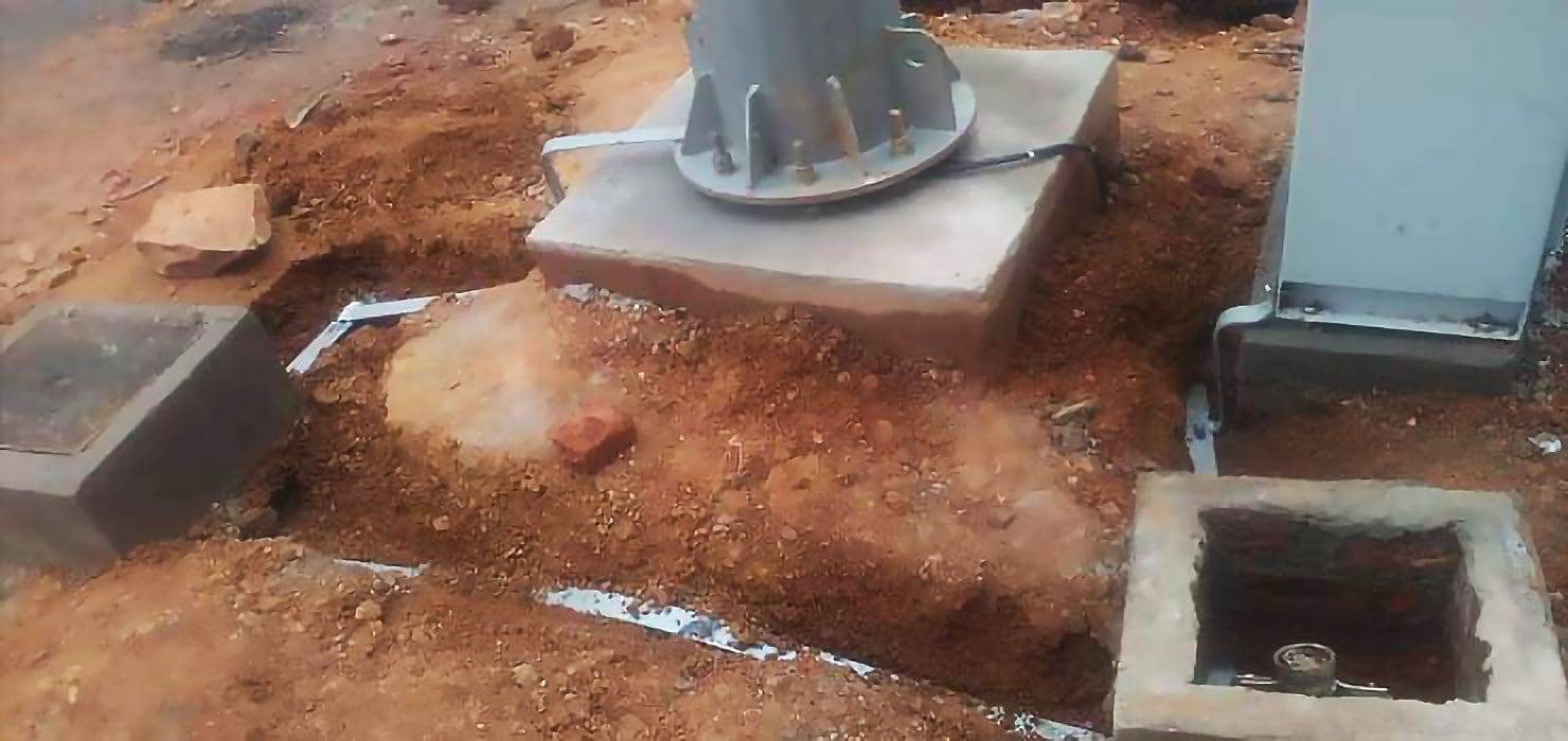
Figure 2 – Current transformer structure fixed to the foundation via anchor bolts
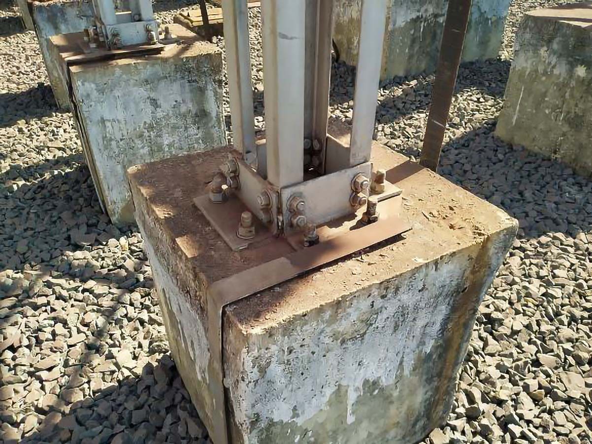
Chemical anchors offer the benefit of being able to locate the support structure and use the holes in the baseplate as a drilling template. However, extra caution is essential to ensure that the supplier’s recommendations are strictly followed to ensure adequate adhesion, as this is highly dependent on the cleanliness of the drilled hole.
A pullout test on a reasonable proportion of the installed quantity is recommended. Because the hole diameter of expansion anchors is typically bigger than that of the bolt holes in the structural baseplate, a separate drilling template is required.
Some cast-in bolts allow for some movement in their position, which can then be grouted into place after the support structure is in place.
The steel framework itself, such the anchor bolts, can also be cast in. In this scenario, the foundation is poured with a pocket to accommodate the steel framework. Before pouring concrete, the structure must be carefully adjusted using some additional setting frames.
Figure 3 – Typical post-installed anchors
The anchor bolt fastening offers an advantage over this type, especially when the lead connections are done with tubular conductors. The structure height can be adjusted here to accommodate for any tolerance in the top of the foundation level.
In addition to the design of the structure-fixing method, foundation design must account for the installation of earth conductors and control cables, whether this is done during foundation installation or after the foundation is installed, using cut-outs, for example.
The alternative strategy of post-pouring provision speeds up and reduces the cost of foundation installation while increasing the cost of following work, but this work will never be in the wrong location because it can be aligned with the established equipment support structures.
In general, the presence of high voltages or huge currents near the foundations has little effect on their construction, but there is one exception: the design of the foundation for air-cored reactors, which generate extremely powerful magnetic fields.
The reinforcing for these foundations must be designed so that there are no closed loops of conductive material by employing insulating material in the joints of traditional reinforcing bars or nonmetallic reinforcing material.
Figure 4 – Transformer foundation with rails

Civil works for transformers or oil-filled reactors must serve four distinct functions:
- To support the transformer and allow it to be moved into and out of service (rails may be required depending on the transformer type).
- To contain any transformer oil leaking. Extinguishing oil fires can also be aided by filling the oil containment area with gravel covered by a top layer of broken stones or by connecting it to an underground tank.
- To decrease the risk of fire propagation (recommended are fire walls and fire barriers in trenches).
- Where necessary, to decrease acoustic noise propagation.
2. Substation Buildings
Substation buildings must be designed in accordance with national and company standards. Their primary function is to contain and safeguard switchgear, protection relays, SCADA equipment, auxiliaries, batteries, fire protection pumps, and so on. The extent of the water, sewage treatment, and accommodation facilities required locally for the operators depends on whether the substation is manned or unmanned.
The accessibility of the substations and the utility’s maintenance methods will determine whether or not a workshop is required, as well as the size of the workshop. The same method is required in evaluating how much maintenance equipment, such as elevating platforms and SF6 handling facilities, should be stored permanently on-site rather than brought to site as needed for specific activities.
In the end, there could be a rationale for installing a transformer un-tanking hall, for example.
Substation buildings can be built using a range of materials, including reinforced concrete, concrete block, brick, clad steel, or steel plate. Depending on building costs or planning constraints, roofs might be pitched or flat. Surface finishes and color treatments may also be influenced by planning needs.
Building design must take into account lifetime costs, particularly in terms of protection against moisture infiltration and corrosion prevention.
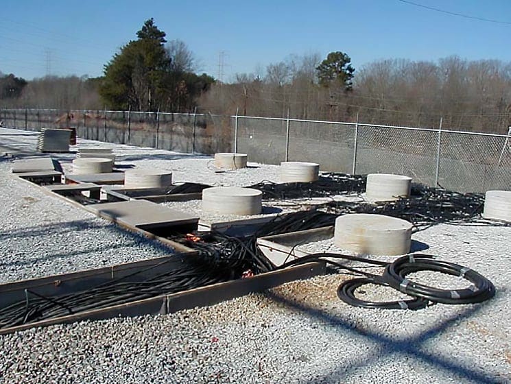
Figure 5 – New piers poured and cables installed before the control house arrives
2.1 Energy Consumption
Buildings in a substation are significant energy consumers. Compliance with the most recent energy efficiency rules could be easily achieved for new structures. Existing building retrofits are more complicated, and energy evaluations should be performed.
Site and site planning, building orientation, wall/roof design, window design, solar heat gain, heating, ventilation, and air-conditioning systems, electric lighting, and landscaping are all examples of energy-saving potential.
Figure 6 – An example of properly ventilated battery room
2.2 Built On-Site or Prefabricated?
Another consideration in building design is whether the structure should be constructed on-site or prefabricated off-site and delivered to the site fully equipped and lowered onto a prepared foundation. For tiny substations, the question can be whether the facility should be regarded permanent or temporary relocatable.
In the case of cabins, containers, or blockhouses utilized for decentralized control and protection equipment, the on-site versus off-site question may be even more significant. Another consideration is whether a building is necessary for each bay or whether each structure can accommodate several bays.
When designing a building, special thought should be paid to flood protection, specifically prevention by the use of an adequate floor level.
Figure 7 – Containerized and prefabricated substations
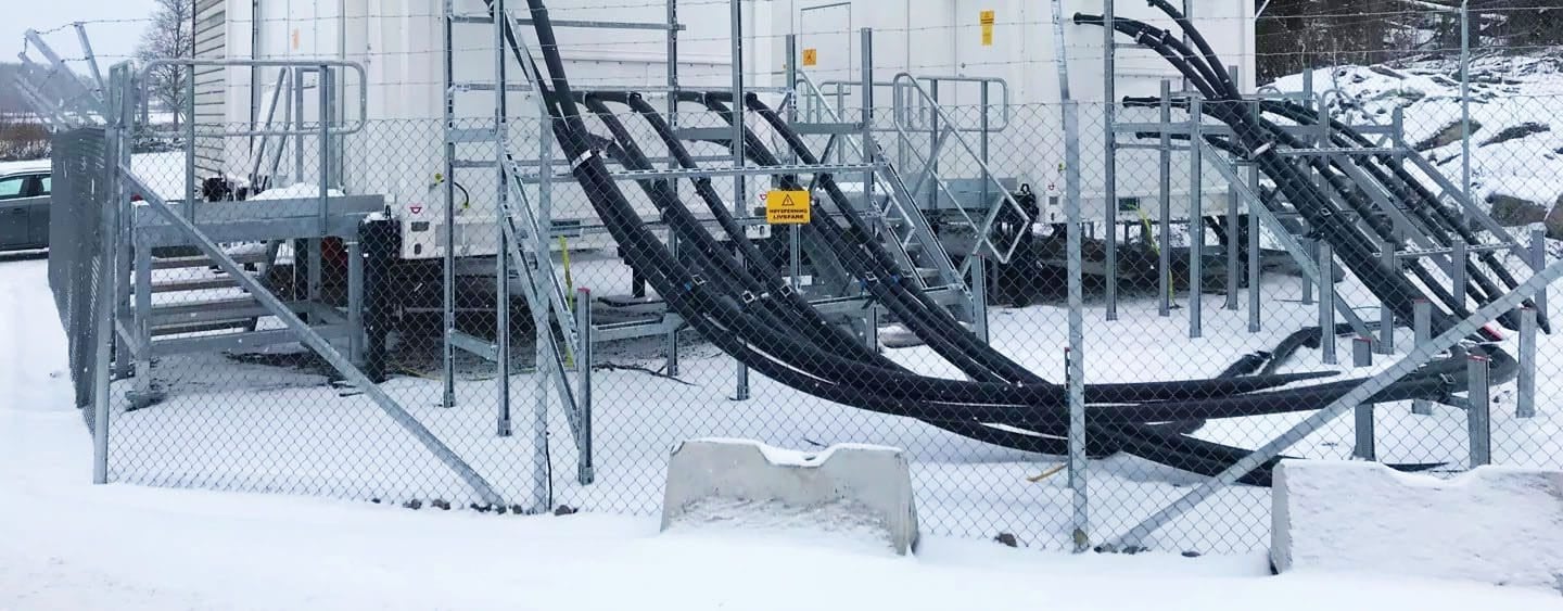
2.3 Control and Power Cables
A related issue is the design of a building’s control and power cable access. This requires extra caution because properly sealing cable openings against water entry is challenging.
Control cable access between equipment cabinets, between rooms, and between the building and the outside must be accommodated in room design. There are two options: overhead routing, in which the cables are routed on cable trays or cable ladders suspended from the ceilings, or below-floor routing, in which the cables are laid either in entirely open sub-floor areas beneath the floor tiles or in surface ducts built into the floor.
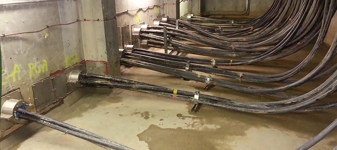
Whatever system is utilized, all points where cables are routed across rooms must be fire-sealed to prevent the spread of fire or smoke.
Figure 8 – Cables entries sealing
2.4 Environmental Requirements
The degree of climate control necessary in substation buildings will be determined by the local climate and the environmental needs of the installed equipment. While interim provisions can be made during building construction, it is advised that environmental conditions within a control building provide suitable circumstances for operational employees.
This may need the installation of climate control technology. In addition to the operational crew needs, several electronic equipment products have relatively stringent environmental requirements in terms of permitted temperature and humidity ranges.
This also applies to batteries, where some have a minimum temperature requirement while others, such as valve-regulated lead acid, lose a significant amount of performance as the ambient temperature climbs above 20 °C.
Such climatic requirements have an impact on building internal layout in that it may be preferable to separate equipment with specific climatic requirements in order to limit the internal building volume that requires specific levels of climate control.
Good Course – Battery Fundamentals: Principles, Terminology, Operations, Design and Hazards
Battery Fundamentals: Principles, Terminology, Operations, Design and Hazards
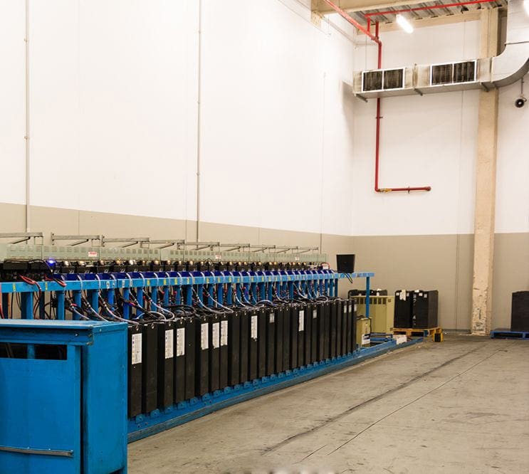
2.5 Batteries
From a different point of view, some pieces of equipment can provide threats that call for them to be kept separate. Because sulfuric acid is used to fill lead-acid batteries and because part of this acid may be emitted as a vapor, the room containing the batteries needs to have surfaces that are resistant to acid.
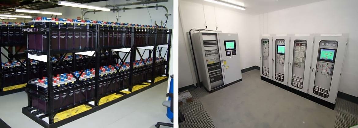
Because of this, it is essential for battery rooms to have capabilities for air circulation and extraction in addition to the emission of hydrogen during the charging process.
Figure 9 – Battery room (left) and battery chargers (right)
2.6 Maintenance
When designing the layout of a structure, it is important to think about how easy it will be to do routine maintenance and how often control or protection equipment would need to be replaced. The building’s basic layout must either provide sufficient slack to accommodate future expansion needs or be conducive to straightforward additions in the future.
Good reading – Secrets and warnings in operation and maintenance of GIS
Secrets and warnings in operation and maintenance of a Gas Insulated Substation (GIS)
2.7 Transformers and Generators
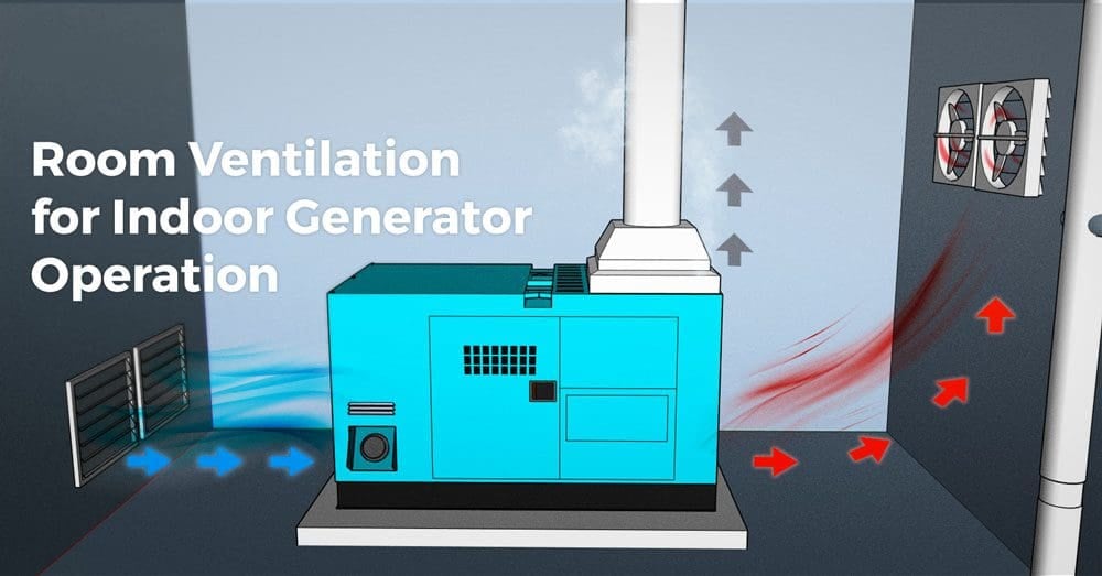
If power supplies are to be located inside a building, rather than outdoors, adequate space must be planned for house supply transformers and/or diesel generators. In the case of dry-type transformers, the only requirements for the transformer room are to provide adequate airflow for cooling, and if the live terminals are accessible, to provide adequate clearances and access control.
Using an oil-filled variety necessitates fireproofing the building, as well as fire extinguishing and containment systems.
It will also be necessary to design the generator base in such a way that vibration from the generator does not go through the structure.
Figure 10 – Room ventilation of indoor generator operation
2.8 Water supply
Water and sanitation facilities should be provided as needed. When deciding what infrastructure to install, it’s important to think about how often workers will need to use the substation and how much it will cost to maintain over the long term.
2.9 Fire Alarm
The SCADA system ought to be connected to a zoned fire alarm system that is suitable for the environment. In order to identify the appropriate level of fire suppression to implement, a risk assessment needs to be carried out.
Figure 11 – Fire-suppression system installed in an control room (3D layout)
3. Trenches for Control & Power Cables
The design of the control cable installation between the individual pieces of HV equipment and the bay marshaling and control point, as well as between the local control/marshaling point and the control building(s), is a significant aspect of the design of an AIS switchyard.
Three broad techniques to cable route design are known. Each of these contrasts the original installation cost with the convenience or cost with which any adjustments to the existing wires, such as installing new cables, can be made.
These are three options:
- Direct-buried cables: Cheap installation/expensive changes.
- Cables placed in pipe ducts: Modest installation costs with sufficient access for alterations if pulling ropes are installed and care is taken with pipe junctions to avoid silt from blocking the pipes and to have enough spare pipes.
- Surface ducts: Expensive installation, but simple access for future alterations. There are two building methods available: site construction with poured concrete or concrete block walls or prefabricated parts produced from some type of glass-reinforced plastic that may be quickly clipped together on-site.
To give a secure foothold, the surface finish should be somewhat roughened. When using potentially buoyant materials, be sure they are securely fastened and will not be moved during a flooding event.
Figure 12 – Cable routes

The design of cable routes must also take into account the requirements for vehicle (sometimes heavy vehicle) access around the switchyard, so either the routes should be completely designed to meet the vehicle loads or designated vehicle crossing points should be provided and clearly marked.
The original provision of cable routes must also account for any additional cables that may be necessary to cater for any future enlargement to the substation, as later installation of new additional cable routes to a control building is likely to be both complex and expensive.
Suggested Guide – A practical handbook for reading and analysing electrical drawings and diagrams
A practical handbook for reading and analysing electrical drawings and diagrams
4. Oil Containment
The location should be chosen to avoid any harm to the natural drainage network, particularly to permanent surface watercourses and groundwater recharge regions, in order to avoid any damage to the subsurface network. All toxic materials in the substation must be used and managed in such a way that they do not seep into groundwater or beyond the substation border. Wherever feasible, the vessels of power and instrument transformers, capacitors, coils, and so on must be leakproof.
In most nations, further safeguards against hazardous compounds are required.
When there is no oil leaking, the rainwater can be evacuated. Otherwise, decontamination via mechanical separation, filtering, or chemical cleaning is required.
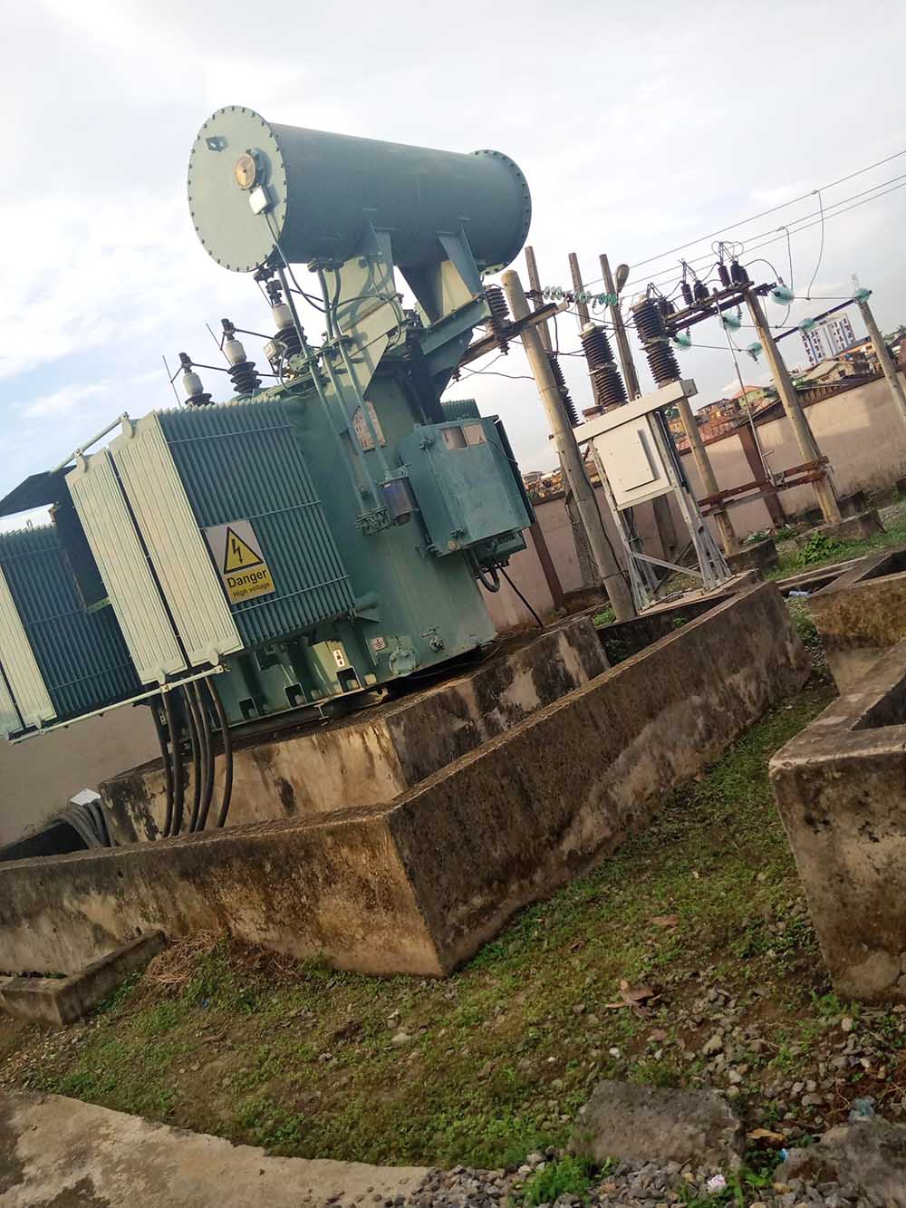
Figure 13 – Transformer oil pit
While big power transformers are the most visible source of oil pollution, all sources must be examined, including diesel generator tanks, substation supply transformers, bulk-oil circuit breakers, and so on.
The likelihood of an oil spill in a substation is extremely minimal. Certain substations, however, have or will have a higher potential for releasing dangerous quantities of oil into the environment due to their proximity to groundwater resources, open water or designated wetlands, the amount of oil on-site, surrounding topography, soil characteristics, and so on.
Increased public awareness of the environmental elements of substations, as well as newer, more strict environmental rules, require utilities to take steps to reduce the environmental impact of new substations in general, but especially the impact of these older substations.
Suggested Course – The Power Substation Fundamentals: Theory, Equipment, Earthing, and Design
The Power Substation Fundamentals Course: Theory, Equipment, Earthing, and Design
Sources:
- Basic Design and Analysis of Air-Insulated Substations by Colm Twomey, Hugh Cunningham, Fabio Nepomuceno Fraga, Antonio Varejão de Godoy, and Koji Kawakita
Related electrical guides & articles


Edvard Csanyi
Hi, I'm an electrical engineer, programmer and founder of EEP - Electrical Engineering Portal. I worked twelve years at Schneider Electric in the position of technical support for low- and medium-voltage projects and the design of busbar trunking systems.I'm highly specialized in the design of LV/MV switchgear and low-voltage, high-power busbar trunking (<6300A) in substations, commercial buildings and industry facilities. I'm also a professional in AutoCAD programming.
Profile: Edvard Csanyi

Edvard, Great article but please change the main picture!
There are so many safety violations it makes me squeamish just to look at it.
Hi Edward
A question about the size of the containment pit. For the volume it is quite clear but what I wonder is if the surface of the pit as to be larger than the transformer?
Thanks.
BR
Jacques
I believe NFPA 850 provides guidelines for transformer oil contaminant on the size. There is an IEEE standard as well but I can’t remember it right now.
Hi Edvard
I enjoy your posts and knowledge-sharing.
I don’t want to be critical, but Figure 13 – Transformer oil pit is most probably one of the best examples of non-compliance. It does not meet any of the oil containment and fire requirements.
Happy to discuss.
Hi Jan,
Thank you for the critical view, I love it! I agree, Figure 13 is not the best picture and does not meet the requirements for the fire protection and the oil containment. I’ll try to find better picture.