Where are ungrounded systems applied
Ungrounded systems are power systems with no intentionally applied grounding. However, they are grounded by the natural capacitance of the system to ground. Thus, the fault current level is very low, such that equipment damage is minimal.

It is not necessarily essential that the faulted area be rapidly isolated. This is an advantage and therefore, it is sometimes used in industrial plant systems where a high continuity of service is important to minimize interruptions of expensive production processes.
Thus, they are generally not recommended, even though they are normally used.
- Faults in ungrounded systems
- Transient overvoltages (as a consequence)
- Grounded-detection methods for ungrounded systems
- Ungrounded System – easily explained (VIDEO)
1. Faults in ungrounded systems
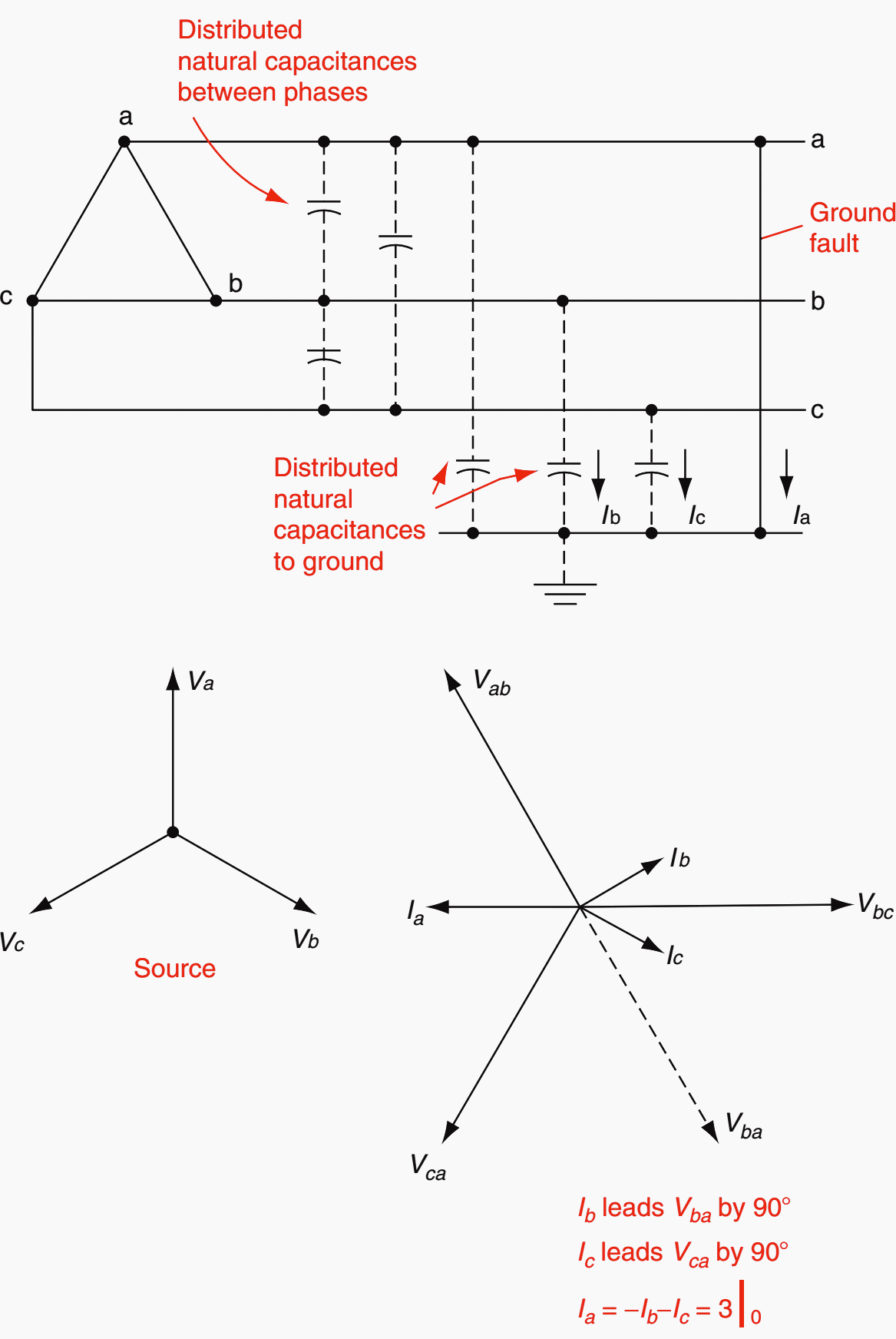
Phase-to-ground faults on an ungrounded system essentially shift the normal balanced voltage triangle, as shown in Figure 1. The small currents flowing through the series phase impedances will cause a very slight distortion of the voltage triangle, but practically, it is as shown in Figure 1b.


A typical circuit is illustrated in Figure 2 showing the current flow.
The sequence networks are shown in Figure 3. The distributed capacitive reactance values X1C, X2C, and X0C are very large, whereas the series reactance (or impedance) values X1S, XT, X1L, X0L and so on, are relatively very small. Thus, practically, X1C is shorted out by X1S and XT in the positive-sequence network, and similarly for the negative-sequence network.
Because these series impedances are very low, X1 and X2 approach zero, in relation to the large value of X0C.


Therefore:
I1 = I2 = I0 = Vs/X0c (equation 1)
and
Ia = 3I0 = 3Vs/X0c (equation 2)
This calculation can be made in per unit (pu) or amperes (A), remembering that VS and all the reactances (impedances) are line-to-neutral quantities.
The unfaulted phase b and c currents will be zero when determined from the sequence currents of Equation 1. This is correct for the fault itself.
This is shown in Figure 2.


If Ia = −1 pu, then Ib = 0.577 ∠+30° and Ic = 0.577 ∠−30°.
In industrial applications where ungrounded systems might be used, the X0C is equal practically to X1C = X2C and is equivalent to the charging capacitance of the transformers, cables, motors, surge-suppression capacitors, local generators, and so on, in the ungrounded circuit area.
Various reference sources provide tables and curves for typical charging capacitances per phase of the power system components. In an existing system the total capacitance can be determined by dividing the measured phase-charging current into the line-to-neutral voltage.
When a phase-to-ground fault positively occurs, the unfaulted phase-to-ground voltages are increased particularly by √3 (see Figure 1b). Thus, these systems require line-to-line voltage insulation.
In the normal-balanced system (see Figure 1a) Van = Vag, Vbn = Vbg, and Vcn = Vcg. When a ground fault occurs, the phase-to-neutral voltages and the phase-to-ground voltages are quite different.
The neutral n or N is defined as ‘‘the point that has the same potential as the point of junction of a group (three for three-phase systems) of equal nonreactive resistances if connected at their free ends to the appropriate main terminals (phases of the power system)’’ (IEEE 100). This is the n shown in Figure 1b.
From this figure, the voltage drop around the right-hand triangle is:
Vbg − Vbn − Vng = 0 (equation 3)
and around the left triangle: Vcg − Vcn − Vng = 0 (equation 4)
In addition: Vng + Van = 0 (equation 5)
From the basic equations,
Vag + Vbg + Vcg = 3V0 (equation 6)
Van + Vbn + Vcn = 0 (equation 7)
Subtracting Equation 7 from Equation 6, substituting Equation 3 through Equation 5, and with Vag = 0:
Vag − Van + Vbg − Vbn + Vcg − Vcn = 3V0,
Vng + Vng + Vng = 3V0,
Vng = V0 (equation 8)
Thus the neutral shift is zero-sequence voltage. In the balanced system of Figure 1a, n = g, V0 is zero, and there is no neutral shift.
2. Transient overvoltages as a consequence
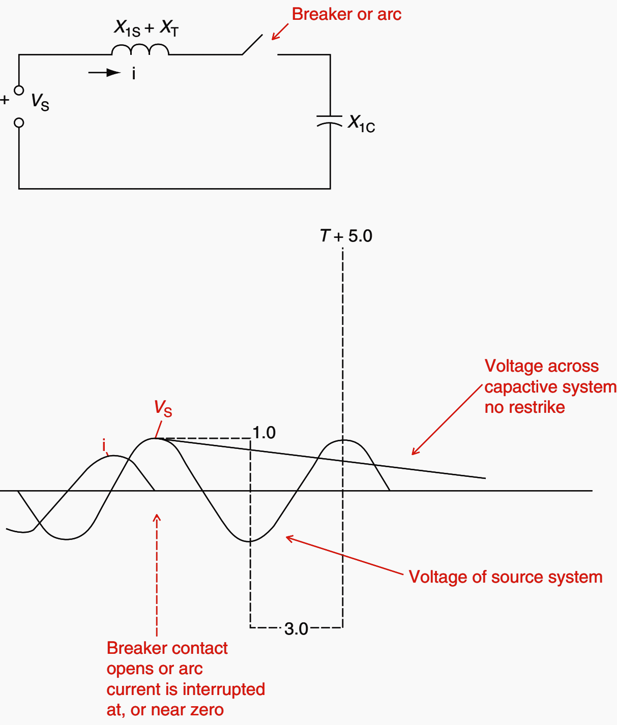
Restriking arcs after current interruption in the breaker or in the fault can result in large destructive overvoltages in ungrounded systems. This phenomenon is illustrated in Figure 4 below.
Thus, in a half cycle, the voltage across the open contact is almost twice the normal peak value.
If a restrike occurs (switch closed in Figure 4), the basic +1 pu voltage of the capacitive system will shift to the system voltage of −1 pu, but because of the system inductance and inertia, it will overshoot to a maximum possibility of −3 pu.


If the arc goes out again near current zero (switch open) but restrikes (switch closed) again, the system voltage will try to shift to +1 pu, but yet another time overshoot, this time to a potential maximum of +5 pu.
This could continue to −7 pu, but, meanwhile, the system insulation would no doubt break down, causing a major fault. Thus, ungrounded systems should be used with caution, and applied at the lower voltages (<13.8 kV), where the system insulation levels are higher.
However, with the fault the other phases are operating at basically 1.73 times the normal line-to-ground voltage. If an insulation deterioration caused the first ground fault, the higher voltages might accelerate the breakdown of the unfaulted phases, to result in a double line-to-ground or three-phase fault.
Then, high fault currents would result, requiring fast shutdown and instant loss of production.
In actual practice totally ungrounded systems do not exist. As soon as a fault detector is applied using one or three voltage transformers, the system is grounded through the high impedance of these devices. The resistance of the relays and associated ballast resistors help in limiting the transient overvoltages, so that very few cases of overvoltage essentially exist.
3. Grounded-detection methods for ungrounded systems
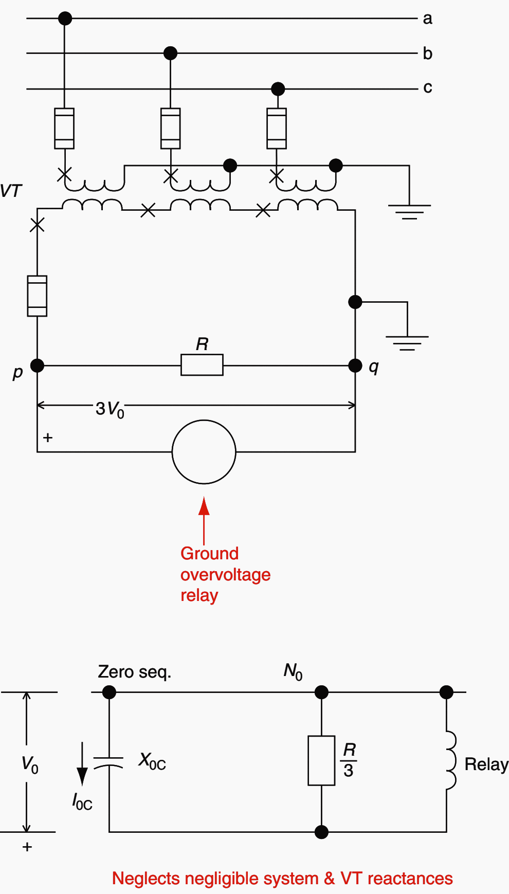
Voltage provides the best indication of a ground fault because the current is very low and, basically, does not change with the fault location. The two methods used are shown in Figure 5 and Figure 6.
These indicate that a ground fault exists but not where it is in the primary system.
3.1 Three-voltage transformers
Wye-grounded–broken-delta voltage transformer connections are preferred (see Figure 5).
Ballast resistors are used to reduce the shift of the neutral from either unbalanced excitation paths of the voltage transformers or from ferroresonance between the inductive reactance of the voltage transformers and relays and the capacitive system.


The voltage for the relay in Figure 5 from Figure 1b is:
- Vpq = 3V0 = Vag + Vbg + Vcg
- Vpq = (√3VLN cos30°) × 2 = 3VLN (equation 9)
Thus, the voltage available to the relay for a phase-to-ground fault on the ungrounded system is three times the line-to-neutral normal voltage.
Figure 5 is simplified. Usually, the voltage transformer will be wye-grounded–wye-grounded and an auxiliary wye-grounded–broken-delta transformer will be used.
Sometimes the main voltage transformer will have a double secondary, one of which can be connected to the broken delta. Lamps can be connected across each broken-delta secondary winding to provide visual indications.
Typical resistance values across the secondary winding, derived from experience, are shown in Table 1.
Table 1 – Typical resistance values across secondary winding
| Resistor R | |||
| Ohms | Watts at 208V | ||
| 2.4 | 2,400:120 | 250 | 175 |
| 4.16 | 4,200:120 | 125 | 350 |
| 7.2 | 7,200:120 | 85 | 510 |
| 13.8 | 14,400:120 | 85 | 510 |
3.2 Single-voltage transformers
The single-voltage transformer of Figure 6 is especially subject to possible ferroresonance, without adequate resistance in the secondary.


Without this resistance Vbg is calculated (equation 10):


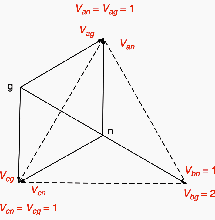
If the distributed system capacitance XC divided by the transformer exciting reactance Xe equals 3, then theoretically, Vbg is infinite. Saturation of the voltage transformer would prevent this, but it is quite possible for the voltage triangle abc to have its ground point well outside this triangle.
This is called ‘‘neutral inversion’’, as illustrated in Figure 7.


and Xe = j2. All values in per unit.
In this case, the ratio of XC / Xe is 1.5, therefore, in Equation 10 above, Vbg = 2.0 pu as shown in Figure 7. For simplicity, resistance neither in the system nor across the voltage transformer secondary isassumed.
This ground detection scheme must be used with caution to avoid ‘‘neutral’’ inversion and ferroresonance, as outlined above. The voltage relay is set to have its contacts held open for the normal line-to-ground secondary voltage.
When a ground fault occurs on phase b, the voltage collapses and the voltage relay resets to close the undervoltage contacts. If a phase a or c ground fault occurs, the relay voltage increases by about 1.73 V to cause the relay to operate on overvoltage.
Either undervoltage or overvoltage operation usually sets off an alarm to alert the operators of a ground fault so that they can arrange an orderly or convenient shutdown.
4. Ungrounded System – easily explained (VIDEO)
This video-series consists of three clips – one explaining the advantages of an IT-system, the second describes what happens in an IT-system in the event of an insulation fault and the last one explains how to locate an insulation fault.
Part 1 – The advantages of an ungrounded system
Part 2 – What happens in the event of an insulation fault?
Part 3 – How do you find ground faults in the ungrounded systems?
Source // Protective Relaying Principles and Applications by J. Lewis Blackburn and Thomas J. Domin (Purchase hardcover from Amazon)


Scenario: a large ungrounded MV system with a charging current well above 10 A and no first fault location devices. What’s recommended in this case to improve the entire system?
In terms of personnel and equipment safety how reliable is the system of using isometer? In terms of cost would such system be really effective (especially in 3rd world countries)? Is isometer already widely use in the operation of electrical equipment or recent technology? Your kind feedback would be much appreciated.
Bismillah. The devise is called A-isometer, isn’t it?
Very good read. I am an HVAC Tech. working in Toronto. I look after some older buildings that have a Open Delta power source to the roof top units. I have seen what happens when a unit causes a ground fault to the phase voltages to ground the raise to 600 to ground on two phases and 0 to ground on one phase. Would like very much to understand why this happens. Any info would be much appreciated. Thanks Mike
To Mike Parise call a Electrician you are over your head
I agree with you. Mike Parise is in waaaaay over his head.
Mike just wants to learn more and asks for that knowledge and you two just tell him he’s over his head. If I had a good answer, I would give it to him. Grow up you two…