
Estimated Study Time: 10 minutes
GIS Grounding Practices
With the exception of SF6-to-air bushings terminals, all active portions of gas-insulated switchgear (GIS) are contained within grounded enclosures, which means that they are not susceptible to inadvertent contact. This makes gas-insulated switchgear intrinsically safe. In addition, numerous grounding procedures are utilized by GIS installations in order to accomplish system and protective grounding.
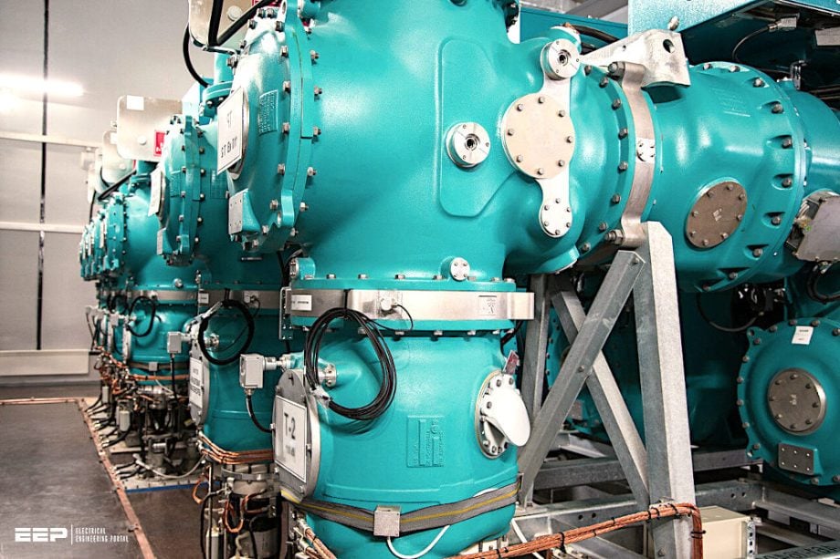 Practical lesson in grounding and bonding of Gas-Insulated Switchgear (GIS)
This is done in order to guarantee the safety of substation personel and to protect equipment.
GIS Versus AIS Grounding
GIS are installed under identical system settings as air-insulated switchgear (AIS). Nonetheless, regarding grounding, a notable distinction is that GIS are typically installed on considerably smaller sites than AIS. Consequently, GIS lack the advantages of extensive AIS switchyards, where the station grounding grid facilitates the dissipation of fault currents.
As a result, to establish low impedance pathways to ground for fault currents, diminish magnetic field intensities, and mitigate transient overvoltages, GIS installations MUST employ multipoint grounding systems.
The numerous grounding conductors offer parallel pathways to the GIS main ground bus or GIS grounding mesh.
Related Guide (PDF) – Best practice in power substation grounding
GIS Enclosure Currents
In the majority of GIS systems, each module is electrically bonded using either flange connections or external shunts. This provides a continuous enclosure within the GIS, facilitating the flow of enclosure currents during standard operations and fault conditions.
Enclosure currents arise from voltages induced in the metallic enclosure due to currents flowing in the enclosed conductors and can be classified as induced, return, circulation, or fault currents.
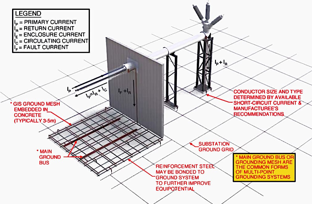
In three-phase GIS applications, enclosure currents are not affected by circulating enclosure currents, as all phase conductors are contained within a single enclosure, resulting in the cancellation of their electromagnetic fields.
Figure 1 depicts the currents within a three-phase enclosure.
Figure 1 – Three-phase GIS enclosure currents
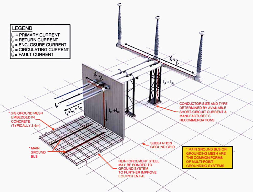
In single-phase GIS, each conductor is housed within its individual grounded enclosure. Consequently, enclosure currents during standard operation consist of circulating currents. GIS manufacturers generally supply conductors to link each single-phase enclosure at multiple locations.
The grounding connections are linked throughout each phase enclosure at intervals along the GIS, including the enclosure ends, to facilitate circulating currents and diminish magnetic fields.
The phase enclosure interconnections prevent substantial circulating currents from passing grounding wires and entering the substation ground grid.
Figure 2 depicts the currents within a single-phase enclosure.
Figure 2 – Single-phase GIS enclosure currents
General Rules for GIS Grounding
According to IEEE Standard 80, touch voltages could pose a greater hazard than step voltages in AIS. The increased availability of equipment in GIS, along with the presence of longitudinal induced voltages on GIS enclosures, necessitates heightened supervision of touch voltages in GIS. To assess the maximum contact and step voltages on GIS enclosures during a fault, an examination of the substation grounding system is required.
Utilize commercially available grounding software to conduct simulations for assessing maximum touch and step potentials, along with ground potential rises.
In the majority of GIS applications, the grounding system comprises two grounding grids.
1. The station grounding grid – which is similar to a typical AIS installation;
2. The GIS grounding mesh – which is a narrowly spaced grounding grid (typically 3–5 meters) embedded into the concrete slab in which the GIS is installed.
Best practices for GIS grounding and bonding include the following:
Practice #1 – All grounding conductors should be as short as possible.
Practice #2 – The grounding mesh and interconnections should be capable of carrying the system’s fault currents without exceeding the thermal and mechanical limits.
Practice #3 – All exposed grounding conductors should be protected against mechanical damage and located so as not to present a “trip hazard” to operation personnel.
Practice #4 – Proper grounding and bonding techniques, such as multiple conductors or voltage limiters, are required at all discontinuities within the GIS.
Practice #5 – Ensure all metallic building components, GIS support structures, and GIS maintenance platforms are properly grounded.
Practice #6 – Reinforcement steel in the building floor should be connected to the GIS grounding mesh to further equalize ground potentials.
Practice #7 – All secondary cables should be shielded with both ends of each cable shield grounded to mitigate possible electromagnetic interference.
Suggested Course – GIS Design, Installation, Operation and Maintenance, Testing
Gas-Insulated Switchgear Course: Design, Installation, Operation and Maintenance, Testing
Very Fast Transients (VFTs)
Very fast transients (or VFTs) are generated as a result of switching operations inside the GIS or a dielectric breakdown that causes a voltage collapse within the GIS. The voltage collapse produces traveling waves that propagate away from the disturbance.
The traveling waves propagate throughout the GIS with various reflections and combine to produce VFTs or overvoltages with a very steep rate of rise.
As VFTs approach discontinuities, they can cause transient enclosure voltages (i.e., TEVs). TEVs do not present a direct hazard to operations personnel, but may cause electrostatic sparks if the GIS multipoint grounding system is not installed properly.
Further Study – How to mitigate effects of very fast transients (VFT) on HV equipment
How to mitigate effects of very fast transients (VFT) on HV equipment
GIS Grounding Connection Details
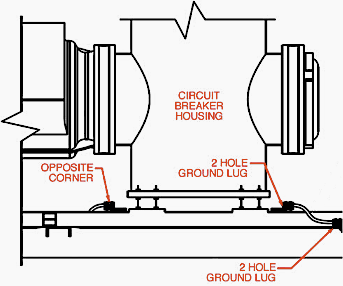
Detail #1 – Circuit breakers: Each circuit breaker should have two connection points for grounding.
Detail #2 – SF6 gas-to-air bushings: Special attention should be given to SF6 gas-to-air bushings where high frequency effects are most prevalent. A minimum of two grounding conductors should be installed.
See Figure 3.
Figure 3 – SF6 gas-to-air bushings
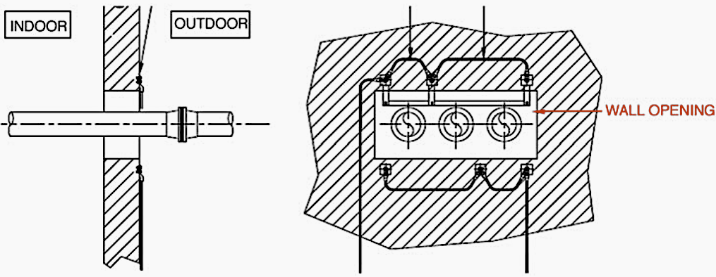
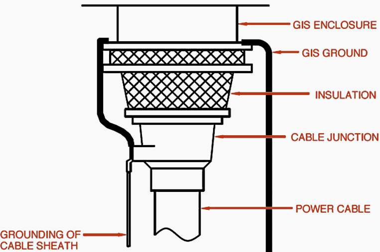
Detail #3 – SF6 gas-to-cable connections: It is important to evaluate the method of grounding at the GIS cable end unit. Multiple conductors may be required if solidly bonded and voltage limiters might need to be considered if single point bonding is used.
See Figure 4.
Figure 4 – SF 6 gas-to-cable connections
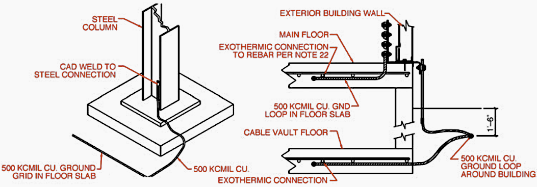
Detail #4 – Steel structures: All steel structures should be grounded. Normally a steel structure can be grounded to the nearest grounding point or GIS flange.
See Figure 5.
Figure 5 – Steel structures
Detail #5 – Buildings: Building slabs should include an embedded GIS grounding mesh and steel reinforcement should be concrete. Reinforced steel should be bonded to the grounding mesh every 3 meters in both directions.
See Figure 6.
Figure 6 – Grounding of GIS buildings
Source: GIS by H. Koch
Related electrical guides & articles


Edvard Csanyi
Hi, I'm an electrical engineer, programmer and founder of EEP - Electrical Engineering Portal. I worked twelve years at Schneider Electric in the position of technical support for low- and medium-voltage projects and the design of busbar trunking systems.I'm highly specialized in the design of LV/MV switchgear and low-voltage, high-power busbar trunking (<6300A) in substations, commercial buildings and industry facilities. I'm also a professional in AutoCAD programming.
Profile: Edvard Csanyi

All the shared articles are very very useful. ..
Thank you, Rajavel. I’m glad you find articles useful!