
Estimated Study Time: 14 minutes
Bonding and grounding explained
All home electrical systems must be bonded and grounded according to code standards. This entails two tasks: First, the metal water and gas pipes must be connected electrically to create a continuous low resistance path back to the main electrical panel. Second, the main electrical panel must be grounded to a grounding electrode such as a ground rod or rods driven into the earth near the foundation of your house.
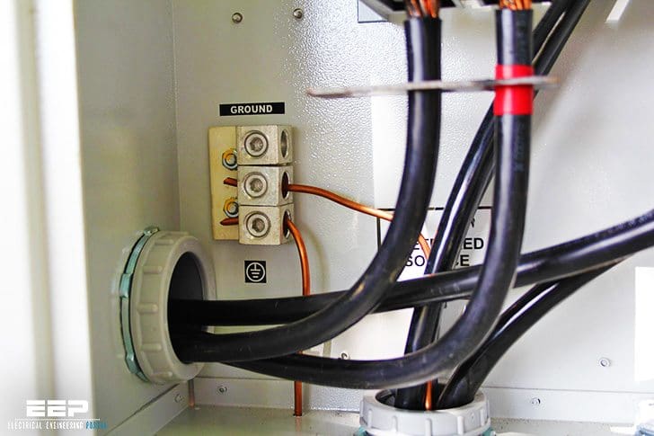 Good practice for grounding and bonding a home wiring system (photo credit: inspectionnews.net)
Although the piping system is bonded to the ground through your main electrical service panel, the panel grounding and the piping bonding are unrelated when it comes to function. The grounding wire that runs from your electrical panel to the grounding electrode helps even out voltage increases that often occur because of lightning and other causes.
Bonding is done relatively efficiently at the water heater, as the gas piping and water piping generally there.
Gas pipe in older homes is usually steel or copper. The bonding connection point for these pipes can be at any accessible location, such as at the water heater or at the gas meter. Gas pipe in some new homes is a flexible material called corrugated stainless steel tubing (CSST).
The bonding point for CSST must be at the first piece of steel or copper pipe where the gas service enters the home. This is because lightning can blow holes in CSST, causing a gas leak.

How to Bond Metallic Piping | 6 Steps
Step #1
Determine the amperage rating of your electrical service by looking at your main breakers. The system amperage (usually 100 or 200 amps) determines the required gauge of the bonding wire you need. #4 copper wire is sufficient for service not exceeding 200 amps.
Smaller, less expensive copper wire is allowed for services between 100 and 175 amps. Check with your electrical inspector if you want to use wire smaller than #4.

Step #2
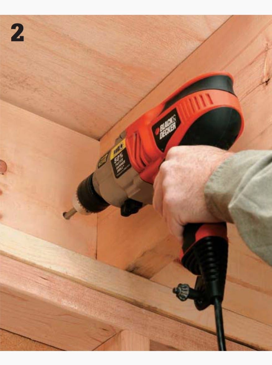
Run the bonding wire from a point near your water heater (a convenient spot if you have a gas-fueled water heater) to an exit point where the wire can be bonded to the grounding wire that leads to the exterior grounding electrodes. This is frequently done at the service panel.
Run this wire as you would any other cable, leaving approximately 6 to 8 ft. of wire at the water heater. If you are running this wire through the ceiling joists, drill a 1⁄2″ hole as close to the center as possible to not weaken the joist. Staple the wire every 2 ft. if running it parallel to the joists.

Step #3
Install pipe ground clamps on each pipe (hot water supply, cold water supply, gas), roughly a foot above the water heater. Do not install clamps near a union or elbow because the tightening of the clamps could break or weaken soldered joints. Also make sure the pipes are free and clear of any paint, rust, or any other contaminant that may inhibit a good clean connection.
Do not overtighten the clamps. Use clamps that are compatible with the pipe so that corrosion will not occur. Use copper or brass clamps on copper pipe. Use brass or steel clamps on steel pipe.

Step #4
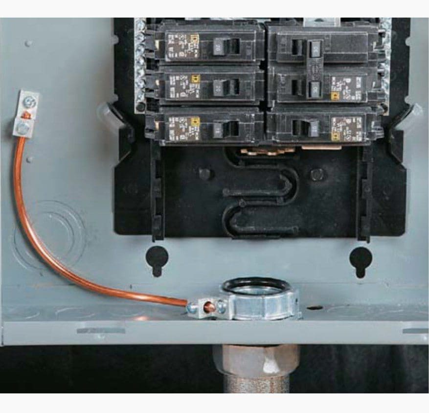
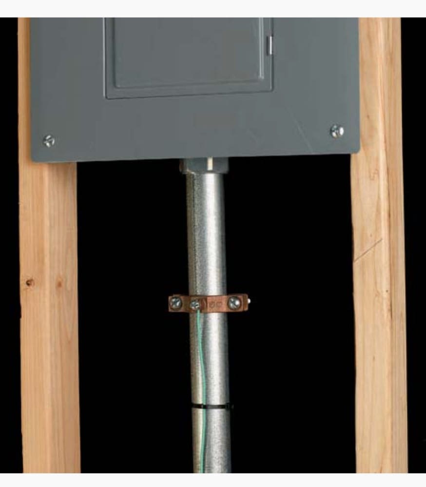
Route the ground wire through each clamp wire hole and then tighten the clamps onto the wire. Do not cut or splice the wire: The same wire should run through all clamps.

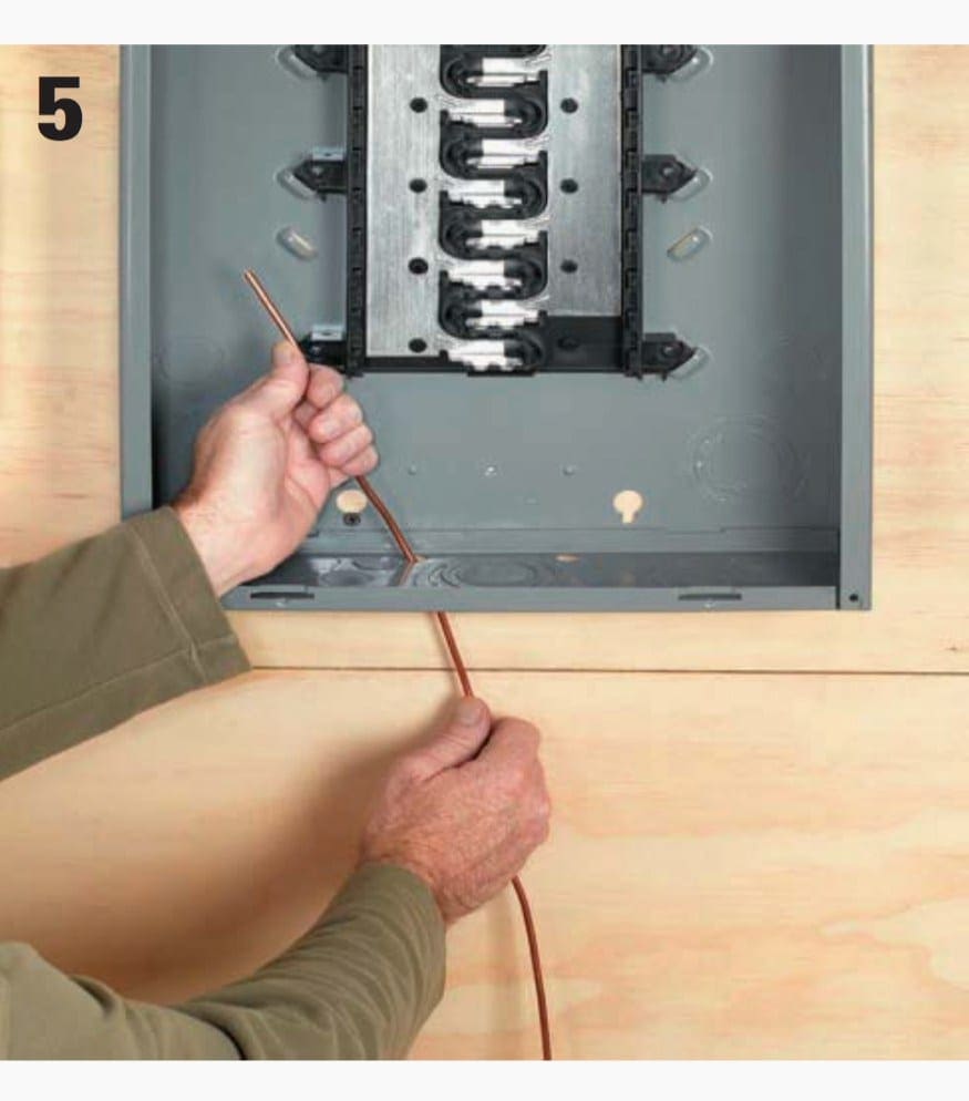
Step #5
At the panel, turn off the main breaker. Open the cover by removing the screws, and set the cover aside. Route the ground wire through a small 3⁄8″ hole provided towards the rear of the panel on the top or bottom.
You will usually have to knock the plug out of this hole by placing a screwdriver on it from the outside and tapping with a hammer. Make sure the ground wire will not come into contact with the bus bars in the middle of the panel or any of the load terminals on the breakers.
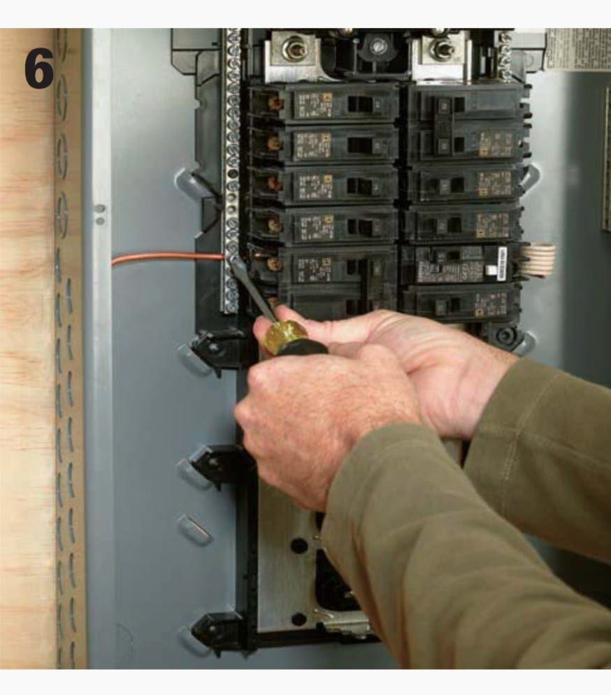
Step #6
Locate an open hole on your ground and neutral bus and insert the ground wire. These holes are large enough to accommodate up to a #4 awg wire, but it may be difficult at times. If you’re having trouble pushing the wire in, trim a little wire off the end and try with a clean cut piece. Secure the set screw at the lug.
Replace the panel cover and turn the main breaker back on.
Tips for Grounding the Main Service Panel
The neutral and grounding wires should not be connected to the same bus in most subpanels. The grounding bus should be bonded to the subpanel cabinet.
The neutral bus should not be bonded to the subpanel cabinet.

Metallic conduit must be physically and electrically connected to panel cabinets. A bonding bushing may be required in some cases, where not all of a knockout is removed.
Ground Rod Installation
The ground rod is an essential part of the grounding system. Its primary function is to create a path to ground for electrical current, such as lightning, line surges, and unintentional contact with high voltage lines. If you upgrade your electrical service you likely will need to upgrade your grounding wire and rods to meet code.
Note! Different municipalities have different requirements for grounding, so be sure to check before attempting to do this yourself. Call before you dig! Make sure the area where you will be installing the ground rods is free and clear from any underground utilities.
Exercise Your Breakers!
Your breakers (including the main) should be “exercised” once a year to ensure proper mechanical function. Simply turn them off and then back on. A convenient time to perform the exercise is at daylight savings time, when you’ll need to reset all of your clocks anyway.
How to Install a Grounding Electrode System
Step #1
Begin by purchasing two copper-coated steel ground rods 5/8″ diameter by 8′ long. Grounding rods have a driving point on one end and a striking face on the other end.

Step #2
Drill a 5⁄16″ hole in the rim joist of your house, as close as practical to the main service panel to the outside of the house above the ground level at least 6″.
Step #3
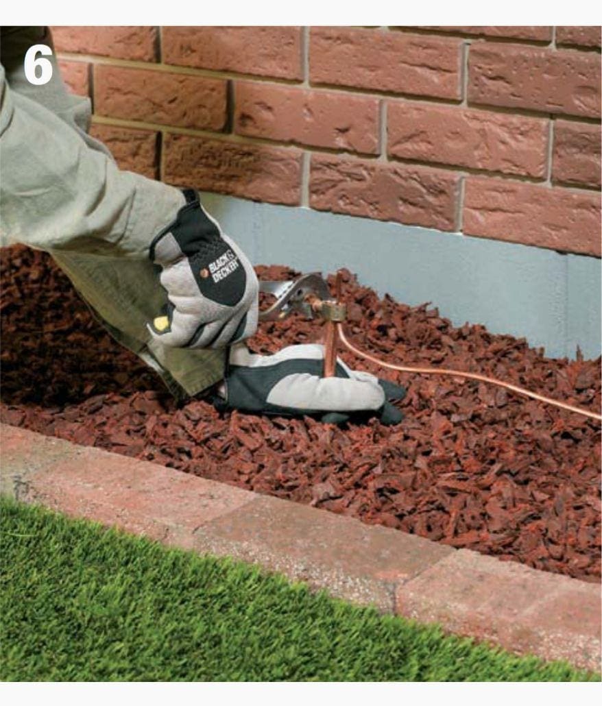
About a foot from the foundation of the house, pound one ground rod into the earth with a five-pound maul. If you encounter a rock or other obstruction, you can pound the ground rod at an angle as long as it does not exceed 45°.
Drive until only 3″ or 4″ of the rod is above ground. Measure at least 6 ft. from the first ground rod and pound in another one.

Step #4
Run uninsulated #4 copper wire from the ground bus in your main service panel through the hole in the rim joist and to the exterior of the house, leaving enough wire to connect the two ground rods together.

Step #5
Using a brass clamp commonly referred to as an acorn, connect the wire to the first ground rod, pulling the wire taut so no slack exists. Continue pulling the wire to reach the second grounding rod, creating a continuous connection.

Step #6
Connect the second ground rod with another acorn to the uncut grounding wire previously pulled through the first acorn. Trim the excess wire.
Step #7
Dig out a few inches around each rod to create clearance for the five-pound maul. Creating a shallow trench beneath the grounding wire between the rods is also a good idea. Drive each rod with the maul until the top of the rod is a few inches below grade.

Step #8
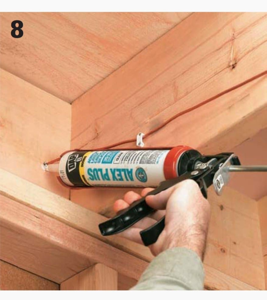
Inject caulk into the hole in the rim joist on both the interior and exterior side.
Tips for Grounding
A listed metal strap may be used to ground indoor communication wires such as telephone and cable TV if an intersystem bonding terminal is not available.
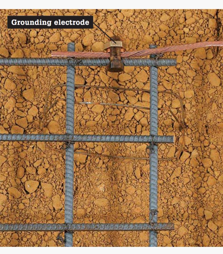
A piece of reinforcing bar encased in a concrete footing is a common grounding electrode in new construction. Called an ufer, the electrode must be No. 4 or larger rebar and at least 20 ft. long. (Shown prior to pouring concrete.)
Reference // The Complete Guide to wiring by Black+Decker
Related electrical guides & articles


Edvard Csanyi
Hi, I'm an electrical engineer, programmer and founder of EEP - Electrical Engineering Portal. I worked twelve years at Schneider Electric in the position of technical support for low- and medium-voltage projects and the design of busbar trunking systems.I'm highly specialized in the design of LV/MV switchgear and low-voltage, high-power busbar trunking (<6300A) in substations, commercial buildings and industry facilities. I'm also a professional in AutoCAD programming.
Profile: Edvard Csanyi

Would it not make more sense to put the ground pipe in the basement below concrete pad with a hole for the pipe, behind the wall just below the breaker panel.
The subsoil will be moister than the 8 ft rod at ground level trying to reach the basement level. Then it can be just say 2 to 3 ft pounded into the ground. This is especially better for clay subsoils and thus shorten the wire resistance and inductance. (0.8 mΩ/m + 1uH/m)
If natural gas is piped from underground with steel pipes would these not be already grounded?
This could apply to all new homes with basements.
Pretty sure it is not an NEC requirement to bond metallic conduit to a metal panel/box. Do you have a code reference for that?
Thank you for all the info.
My question is does the NEC allow you to use one conductor un spliced correctly sized for ground fault from the service panel ground bar to be electrically connected to the ground rods (2) and the the same conductor to continue to the water pipe hot and cold and then to the gas line?
My son says my home needs to be bonded. Who can i call that will do this correctly??
You call a bond wire and a ground wire the same thing. This is incorrect!
“Ground” is defined as zero volts only at one point, regardless if it is PE or a floating battery -V. By design, “ground” is extended from this point where you expect 0V within an acceptable tolerance for any expected conduction. Designs use ground planes to reduce inductance and resistance. The protective earth (PE) bond wire can be considered a ground wire only the conductance and inductance provides an expected safe voltage rise with the expected current conducted. There are ground PE wires distributed thought the home and in America these terms are often casually equated but understood not the same.
Ground voltage = 0V for the ground point and ground wire or bond wire connected to this reference point..
But not “all” ground wires are protective earth bond wires. They could be a floating charger ground wire.
Not all Bond wires are at the same voltage around the world either ;) but they are 0V at chosen reference point during measurements defined as “ground”.
So I agree not all “Ground wires” are bond wires, but it is acceptible to call a bond wire a ground wire.
You redact,good technical articles…thank you.
grounding a gas meter is illegal here where the gas pipe underground is yellow plastic pipe, there’s a wire near the pipe which is NOT a ground wire but a metal wire to use a metal detector to locate the plastic gas line. Anywhere that metal wire touches the plastic gas line will melt the gas pipe if lightning hits and it’s bonded/grounded
Es importante conocer los pasos de un puesta a tierra, en los diferentes entornos de la industria e instalaciones de gobierno.
Boa noite o conteúdo técnico e muito bom Parabéns, ótimo trabalyo
Hi! What is the value of impedance for this kind of grounding system? Was this grounding system calculated and made for any season (winter, summer)? Is it safe to put the wire along the wooden beams without a gap considering the fact that it (the wire) can bring sum current (that warms up the wire) while a cable neutral wire is disconnected (by mistake or burned down for example) from a transformer neutral in the TN-C-S grounding system? How to choose main grounding wire section (wire between earthing electrode and PE bus bar) ? or it is the same for any house regardless wires section size of supply cable.
Thanks Edvard, An interesting article on N. American practice.
For readers in the rest of the world, it might be useful to provide a link to a table that translates measurements such as #4 AWG into metric (and even imperial !) equivalents.
The article specifies use of bare wire, but in many countries, bonding conductors bonding wires & the wire to the grounding electrode(s) have to be insulated – normally green/yellow. I think there’s some justification for this: unskilled people tend to treat an insulated conductor with more respect than they would a bare wire.
It’s also worth pointing out that for urban locations in many countries driven electrodes are not regarded as essential. If a service is delivered via underground cable, the utility company often provides a grounding connection via that cable & a separate rod isn’t obligatory – provided of course that the phase-to-ground loop is verified to have a low enough impedance.