
Estimated Study Time: 31 minutes
Mine power distribution system
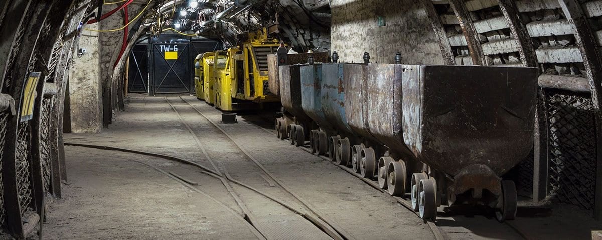
The application of electricity to the mining industry is a distinctive area of both mining engineering and electrical engineering. The difficult environment, the dynamic power loads, the cyclic and mobile operation and stringent safety requirements that characterize mining, all place unique demands on the mine power system.
 Grounding of mine power distribution systems (on photo: underground mine substation; credit: ie-corp.com)
For the coal mining industry, a suitable grounding system has always been a difficult problem, more complex and difficult than in other industries.
No other industry makes such extensive use of portable extensible equipment or has such complex grounding problems. Mine power systems can range from relatively simple installations for small surface mines to complex underground systems where the harsh environment of dust, humidity, and cramped spaces stretches the ingenuity and creativity of the engineer to provide reliable service.
A vital part of any mine power distribution system is the connection to earth or ground, which is referred to as the mine grounding system. This is what we will discuss here.
1. Purposes behind grounding the system
Mine grounding system consists of grounded or grounding conductors, extending from ground beds to equipment. A grounded conductor is a power conductor tied to the grounding system; a grounding conductor is separate from the power conductors and is used only to ground exposed metallic parts of the power system.
A ground bed, also termed a ground mesh or grounding electrode, as well as other names, is a complex of conductors placed in the earth to provide a low-resistance connection to “infinite” earth. The grounding system serves to protect personnel and machinery from the hazards associated with electrical equipment that is operating improperly.
The protection afforded can be divided into the following four functions, which are the main purposes behind grounding the system.
First, the grounding system must limit potential gradients between conducting materials in a given area. During a ground fault, for instance, a phase conductor comes into contact with a machine frame, and current flows through the equipment; subsequently, the potential of the equipment tends to become elevated above ground potential by a n amount equal to the voltage on the conductor.
The maximum potential to which a person could he exposed when touching a machine frame is equal to the voltage drop along the grounding conductors. Thus, the grounding system must provide a low-resistance path for the fault current to return to the source, and the ground conductors should have low resistance so they can carry the maximum expected fault current without excessive voltage drop.
An example of the exposed potential in a surface mining situation is illustrated in Figures 1 and 2.
Figure 1 – Illustration of electrical shock hazard: Three-phase diagram

Second, the grounding system should limit the energy available at the fault location. Heavy arcing or sparking can ignite nearby combustible material. The air itself can become ionized, making it capable of carrying tremendous amounts of current. A high-energy fault can vaporize breakers, switchgear, and phase conductors, and protective enclosures may be blown apart with explosive force.
Controlling the maximum allowable fault current significantly reduces the danger of fire and holds equipment damage to a minimum.
Third, the control of overvoltages is essential. An overvoltage condition may occur by accidental contact of equipment with a higher voltage system, or from transient phenomena due to lightning strokes, intermittent ground faults, autotransformer connections, or switching surges.
Figure 2 – Illustration of electrical shock hazard: Circuit for line-to-ground fault
The maximum ratings for cable insulation, transformer windings, relay contactors, and so forth may be temporarily exceeded in these cases. This does not usually result in an immediate breakdown of equipment, but component parts of the electrical system are successively overstressed and weakened by repeated exposure.
This leads to premature failures, reduced component life, and mysterious “nuisance trips”, which can occur without apparent reason. By providing a path between the transformer neutral and ground, most of the sources of transient overvoltages can be reduced or possibly eliminated.
If the relative tripping levels and speeds are not established correctly, nearby breakers may not trip when they should, and a small problem could escalate into a large calamity. Consequently, power to half a mine may go out because of poor relay coordination, and much time could be lost in the effort to trace and locate the trouble spot.
Thus, the relaying system must be arranged so, even at the lowest level of the power-distribution chain, sufficient fault current can flow to enable the protective circuitry to sense it and take remedial action.
Suggested Reading – The mystery of nuisance tripping incidents in transformer protection that worry engineers
The mystery of nuisance tripping incidents in transformer protection that worry engineers
Go back to the Contents Table ↑
2. Grounding systems
Over the past few decades, several different grounding philosophies have held sway in the electrical industry, each with its own advantages and disadvantages. These methods of grounding are discussed below.
Note that reactance-grounded systems are not presented in the following paragraphs, as they are not normally used in industrial power systems.
Go back to the Contents Table ↑
2.1 Ungrounded Neutral
The ungrounded system was probably the first to be used because of its simplicity. Here there are no intentional ground connections in the system whatsoever. However, a perfect ungrounded system cannot exist, since any current-carrying conductor may be coupled to ground through numerous paths, including the distributed capacitance of its wiring, or through motor windings.
This phenomenon is shown in Figure 3.
Figure 3 – Capacitance coupling in ungrounded system

The first line-to-ground fault on such a system will have very little effect because there is no way for the fault current to find a complete circuit back to the source, and its magnitude will be very small or nil. Very low fault current means no flash hazard and no equipment damage.
Circuit operation continues normally with no interruption of power, an important consideration in industries where downtime is critical . The first fault is often hard to locate because its effects are negligible.
Often no repair effort is made until a second fault occurs, with its concomitant hazards of arcing, heavy current flow, and equipment damage. Since
the entire system is “floating”, there is no control of transient overvoltages. Except for the problem of accidental contact with a higher voltage system, all the other overvoltage sources mentioned previously are enhanced because of distributed capacitance to ground.
Further study – Ground faults in ungrounded systems (risks & detection)
Go back to the Contents Table ↑
2.2 Solidly Grounded Neutral
An alternative is the solidly grounded neutral. The first ground fault produces a substantial neutral current flow, which may be quickly sensed by protective circuitry, thereby shutting down the bad section.
Overvoltages are controlled since the system, as illustrated in Figure 4, now has its neutral solidly referenced to ground. The hazards of this system are due to the magnitude of the fault current. Detection equipment must be sensitive enough to detect low-level fault currents and fast enough to disconnect bad circuits before heavy faults can disrupt system integrity.
Large fault currents, typically several thousand amperes, can explode protective enclosures, destroy equipment, and start fires, which is an excellent reason for not using this technique in explosive atmospheres.
Figure 4 – Solidly grounded system
Go back to the Contents Table ↑
2.3 Low-Resistance Grounded Neutral
The low-resistance grounded-neutral system is established by inserting a resistor between the system neutral and ground. The resistance is such that ground-fault currents are limited from 50 to 600 A, but are commonly about 400 A.
Transients are controlled by the ground connection, and ample fault current is available for actuating protective relays. The flash hazard is not as serious as in the solidly grounded neutral system, but a current flow of 400 A can still do considerable damage. To limit damage, the least sensitive ground relay should respond to 10% of maximum ground-fault current.
A schematic diagram of this method is shown in Figure 5.
Figure 5 – Resistance-grounded system
Go back to the Contents Table ↑
2.4 High-Resistance Grounded Neutral
Perhaps the best technique, and that required by law in coal-mining applications on portable or mobile equipment, is the high-resistance grounded system, often referred to as the safety ground system. The neutral grounding resistor is sized according to the system voltage level, in general to limit ground-fault current at 50 A or less.
Where the line-to-neutral potential is 1,000V or less, the grounding resistor must limit fault current to 25 A or less; above 1,000 V, the voltage drop in the grounding circuit external to the resistor must be 100V or less under fault conditions. With this system, sensitive relaying must detect faults on the order of a few amperes to provide fault isolation and facilitate quick location of the trouble spot. The level of fault current is also low enough to practically eliminate arcing and flashover dangers.
The ground connection also serves to limit the amplitude of overvoltages. However, loads cannot be connected line to neutral, as the grounding conductor must not carry any load current.
Further Reading – Transformers and equipment in underground distribution systems
Transformers and equipment in underground distribution systems
Go back to the Contents Table ↑
3. Electric shock
For a safe grounding system to be efficiently and economically designed, voltage and current levels that are harmful to human beings must be determined. With the trend toward larger and more powerful mining machinery, distribution voltage and current levels have risen proportionately.
Constant vigilance is required when using electricity if the hazard of electrocution is to be avoided. Even if a shock is nonlethal, involuntary movement caused by the shock may lead to serious injury or death.
From this, it can be seen that the human “internal power supply” operates at about 50 Hz, which is exactly the frequency of the electric power generated in Europe. and is only 10 Hz removed from the U.S. power generation frequency of 60 Hz. This is an unfortunate coincidence, for tests have shown that the most dangerous frequencies to which a person can be exposed are power frequencies in the range of 50 to 60 Hz.
Further reading – 11 deadliest mistakes in a power substation made by young and unmindful electrical engineers
11 deadliest mistakes in a power substation made by young and unmindful electrical engineers
Go back to the Contents Table ↑
4. Characteristics of mine grounding systems
The concept of protecting mine electrical equipment and personnel against the consequences of ground faults by suitable grounding has existed since electricity was first introduced into coal mines. For the coal mining industry, a suitable grounding system has always been a difficult problem, more complex and difficult than in other industries.
Go back to the Contents Table ↑
4.1 Ground Beds
For mine usage, the electrical distribution cables and overhead transmission circuits carry into the mine one or more grounding conductors in addition to the phase conductors. Each piece of AC equipment has its frame solidly connected via these grounding conductors to a safety ground bed commonly located near the main surface substation and consisting of buried horizontal conductors or driven rods, or a combination of both.
The neutral of the substation transformer secondary is also connected to the safety ground bed through the neutral grounding resistor, as shown in Figure 6.
Figure 6 – Simplified single-line diagram of substation
It should be noted that for the sake of simplicity, many important components are missing from this diagram.
The substation actually requires two ground beds, maintained some distance apart. Lightning discharges and other transformer primary surging conditions are directed to the system or station ground. The system and safety grounds must be kept separate so current flow intended for one will not enter the other.
Depending upon the physical extent of the grid, a person walking through the area underlain by the grid could bridge a lethal potential gradient with his or her feet. Metallic objects within the potential gradient field can also be elevated to dangerous potentials and become lethal to the touch.
Typical step and touch potentials are illustrated in Figures 7 and 8.
Figure 7 – Step potentials near grounded structure
These step and touch potential hazards are applicable to both the system and safety ground beds. However, the dangers of a high-resistance safety ground bed are not found close to the bed but at the mining equipment.
Figure 8 – Touch potentials near grounded structure
The most insidious feature of the safety ground system is that the equipment connected to it is maintained not at earth potential, but at the safety ground-bed potential. Unless the bed has low resistance, any safety ground-bed current flow can render every piece of mine equipment potentially lethal.
The flow can be created by faults to earth, coupling from lightning strokes to the system ground, lightning strokes to safety grounded machinery, and stray currents from DC haulage systems.
Three such cases are illustrated in Figures 9, 10, and 11. Consequently, with high-resistance ground beds, an elevated frame potential is a problem not just on the machine where it occurs, but everywhere.
Figure 9 -Line-to-earth fault resulting in current flow through safety ground bad

Figure 10 – Lightning stroke to equipment causing current flow through safety ground bed
Figure 11 – Lightning stroke current through system ground bed causing elevation of safety ground bed

Go back to the Contents Table ↑
4.2 Grounding in Underground Mining
Early practice in underground coal mining was to drive a metal rod into the mine floor and use that as a ground. In almost every case this arrangement proved to be totally unacceptable, with test measurements indicating 25Ω or more resistance. With the exception of pumps, the contact resistance of mining machinery with the mine floor also proved to be too high for adequate grounding.
Rail haulage track systems, even though often poorly bonded, showed much lower resistance to ground than most metallic rods driven specifically for that purpose.
A simple form of the bipower (mixed AC-DC) system in use in underground coal mines is illustrated in Figure 12.
Figure 12 – Single-line diagram of simplified mine power system

After transformation, three-phase AC power enters the mine to supply the various three-phase AC loads. Some of the AC power is converted to DC at rectifier stations to power the locomotive system and, occasionally, DC face equipment. More often, any DC face machinery is powered from rectifiers located in the mine section.
Except for the trolley system, all DC as well as the AC equipment frames are connected to a common junction, which is tied to the surface safety ground bed. In order for the system to be effective, grounding conductors must be continuous and this continuity must be verified. Ground-check monitors ensure this.
Trolley locomotives generally utilize the overhead trolley wires as the positive conductor and the tracks as the negative. Neither of these is tied to the rectifier station frame ground. However, because the track is in contact with the mine floor, the negative conductor for the trolley system is grounded.
Even with all these grounding points, the AC grounding system must be isolated from separate DC power systems. If it is not, DC may appear in the AC grounding system, thus elevating it above true ground potential. If an AC ground current is present, it will be offset by the DC level.
The principal concern is with trolley installations, where isolation is achieved by having no common points between the AC and DC systems. Various techniques have been tried to maintain separation or to eliminate DC offsets while grounding DC face equipment frames.
Suggested course – Power Engineering Course: Relay Control and Protection For LV/MV/HV Switchgear
Power Engineering Course: Relay Control and Protection For LV/MV/HV Switchgear
Go back to the Contents Table ↑
4.3 Face Equipment Grounding
When a working section utilizes an AC continuous miner energized from a section power center and DC shuttle cars powered from the trolley system, the ground potentials of the DC and AC equipment frames are not necessarily equal, because of the voltage drop in the track.
This problem could be solved by isolating the low-voltage AC neutral point from the power-center frame and also the high-voltage grounding system, and connecting it via an insulated cable to the track, as shown in Figure 13.
Figure 13 – Mixed AC/DC mine power system; DC load energized from trolley system
The low-voltage neutral point remains connected to the AC face-equipment frames. This technique should make the low-voltage AC and DC equipment frame potentials the same, thus eliminating DC offset problems. Difficulties can still arise with this method. If any track rail bonds are bad between the AC and DC low-voltage ground points, the DC frame potentials might be elevated with respect to the AC frames.
Further, the power center must be constantly maintained at a safe distance from the tracks to preserve isolation between the track and high-voltage grounding systems.
Suggested study – Handbook for application of neutral earthing resistors (NERs) at the substation
Handbook for application of neutral earthing resistors (NERs) at the substation
Go back to the Contents Table ↑
4.4 Track Grounding
As previously mentioned for trolley systems, the rectifier frame is grounded by the AC system, but the negative conductor is grounded to the mine floor through the track. In order to maintain isolation, there is no internal connection between the rectifier output (or the trolley distribution system) and its frame.
However, if the rectifier is sitting on the mine floor, there is a possible common point from the track (DC) to the rectifier frame (AC). Ideally, the common point through the earth is a much higher resistance than the rail itself so that all rectifier current returns in the rail.
Leakage of trolley-wire insulator to the roof or rib may have the same effect, although it is less common. This lack of effective separation can cause DC offset currents on any mining machine and electrical system whenever the sum of the mine floor resistance and equipment frame contact resistances is too low and, therefore, DC current flow is permitted through the earth.
Figure 14 – Mine rail track
To help minimize any problems, rectifiers should be located no closer than 25 ft from the track. In severe cases, the rectifier frame can be insulated from the mine floor.
The preceding has shown that haulage conversion units are the primary source of DC offset currents. Regardless of the source, once stray DC currents occur, they can exist on all the AC grounds within the mine. This problem is further complicated since these currents may also travel through water pipes and hoses, or anything conductive.
While they are touching, a current flow is possible, but when they separate, arcing may occur.
Suggested reading – Practical troubleshooting of power interruption in fully operational 33/11 kV substation
Practical troubleshooting of power interruption in fully operational 33/11 kV substation
Go back to the Contents Table ↑
4.5 Grounding in Surface Mines
The typical grounding system for a surface coal mine is similar to that for underground mining. One or more substations with resistance-grounded secondaries are employed to transform the incoming utility voltage to the lower potential used by the mining machines. At this level, pit distribution is carried on overhead lines or cables to supply switchhouses located near the particular piece of equipment.
A trailing cable completes the power circuit from the switchhouse to the machine. A switchhouse is sometimes connected via cable to a portable substation, which supplies lower voltage power to production, auxiliary, or lighting equipment.
Substation grounding includes both a system and a safety ground bed, each physically removed and electrically isolated from the other. Grounding conductors extend from the safety ground bed to all equipment frames. The neutrals of the transformer secondary of portable substations are resistance grounded to the equipment frame.
Figure 15 – Pit mine substation and switchhouse

In contrast with underground coal mines where the entire secondary distribution system is underground, both the primary and secondary lines in a surface mine are out in the open where they are exposed to lightning. In fact, equipment such as draglines and shovels are subject to direct strokes (see Figure 10).
For the best possible protection from lightning, it is essential that the grounding system have as low a surge impedance as possible. The key factor
here is to provide many short, direct paths to earth.
Go back to the Contents Table ↑
Source: Mine power systems by By L. A. Morley
Related electrical guides & articles


Edvard Csanyi
Hi, I'm an electrical engineer, programmer and founder of EEP - Electrical Engineering Portal. I worked twelve years at Schneider Electric in the position of technical support for low- and medium-voltage projects and the design of busbar trunking systems.I'm highly specialized in the design of LV/MV switchgear and low-voltage, high-power busbar trunking (<6300A) in substations, commercial buildings and industry facilities. I'm also a professional in AutoCAD programming.
Profile: Edvard Csanyi

Good materials in case of electrical engineering….