For engineers and protection specialists
In this technical article, we will delve into the comprehensive methodology of calculating the differential relay settings for the GE P642 relay. Each step of the process will be explored, from data collection to final setting determination. By following these calculations meticulously, engineers and protection specialists can ensure the optimal performance of the relay in differential protection configuration.

Differential protection is a vital element in ensuring the reliable operation of power system equipment, particularly transformers. The GE P642 protection relay offers advanced differential protection capabilities, allowing for precise and effective fault detection. To harness the full potential of this relay, it is crucial to understand the process of calculating the appropriate relay settings.
The article will cover essential topics such as transformer full load currents, variations in current ratios caused by tap changer windings, calculations of CT secondary currents corresponding to high voltage (HV) and low voltage (LV), and the calculation of the ratio correction factor.
Furthermore, we will dive deep into the intricacies of bias current in differential protection, differential pickup current calculations, and differential slope calculations. To enhance the reliability and performance of the differential protection scheme, the article will discuss additional features such as current transformer supervision (CTS), high-set differential protection function, and harmonic blocking (both second and fifth harmonics).
Additionally, stability checks for through fault conditions will be explored, providing insights into verifying the stability of the differential protection settings during such scenarios.
So, let’s embark on this informative journey, exploring the intricacies of calculating the GE P642 relay’s settings for differential protection configuration.
- Data collection for calculating GE P642 relay settings in differential protection configuration
- Calculation of transformer full load currents
- Variations in current ratios due to tap changer windings
- Transformer through fault current calculation
- Calculations of CT secondary current corresponding HV and LV
- Ratio correction factor calculations
- Calculations of HV & LV current at extreme tap positions
- Bias Current in differential protection
- Calculations of differential pickup current
- Differential slope calculations
- Current transformer supervision (CTS)
- High-set differential protection function
- Second harmonic blocking [Ih2%>)
- Fifth harmonic blocking (Ih5%>)
- Stability checks for through fault condition
- Concluding the Final Setting of 87T (protection relay P642)
- BONUS! Differential relay settings paper and presentations (PDF)
1. Data Collection For Relay Settings
Calculating GE P642 Relay Settings in Differential Protection Configuration
The initial phase of configuring the settings for the differential protection relay involves gathering data, and to accomplish this, we have opted to use a 100 MVA Power Transformer. The selected transformer corresponds to the real transformer installed in the field, and the settings are computed specifically for the GE P642 Differential Protection Relay.
Table 1 – Transformer and CT details
| No. | Description | Rating |
| 1 | Transformer rating | 100 MVA |
| 2 | HV side voltage | 132 kV |
| 3 | LV side voltage | 33 kV |
| 4 | Vector group | YNd1 |
| 5 | Impedance | 12.5 % |
| 6 | HV side current | 437.4 A |
| 7 | LV side current | 1749.5 A |
| 8 | Tap range | ±10% |
| 9 | Primary CT ratio | 500/1 A |
| 10 | Secondary CT ratio | 1800/1 A |
2. Calculation of Transformer Full Load Currents
After the data collection stage, the next step involves calculating the full load currents at the high voltage (HV) and low voltage (LV) sides of the transformers. The following formula will be utilized to compute the full load current of the transformers at both HV and LV sides:
S = √ 3 V × I
Here, S is transnformer rating, V is voltage and I is current.
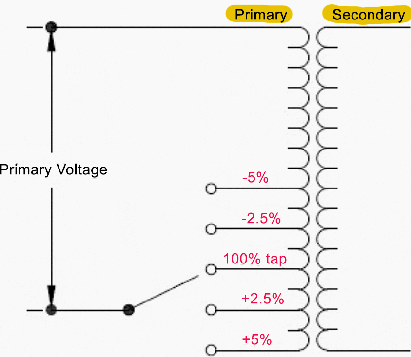
For example if system HV rated voltage is 132kV and actual voltage is also 132kV then when transformer is at the normal tap then rated 33kV voltage will be available at LV side.
Figure 1 – Transformer taps


Normal tap is also referred to as the 100% tap, Taps located above this point are referred to as positive taps, while those positioned below it are known as negative taps.
Calculations of HV Full Load Amperes (HV FLA):
| HV full load current can be calculated as: | S = 100MVA |
| HV voltage = 132kV | |
| HV full load current = IHV | |
| Hence, Transformer HV FLA at nominal tap: | P / √ 3 V = |
| 100000 / (√3×132) = 437.4 A |
Calculations of LV Full Load Amperes (LV FLA):
| LV full load current can be calculated as: | S = 100MVA |
| LV voltage = 33 kV | |
| LV full load current = ILV | |
| Hence, Transformer LV FLA at nominal tap: | P / √ 3 V = |
| 100000 /(√3×33) = 1749.5 A |
Here, it can be seen that there is a difference between HV and LV current at the given MVA rating of the transformers. A transformer may change the voltage or current levels but the apparent power will remain the same for HV and LV windings.
However, modern relays are numerical relays with the capability of a microprocessor, and as a result, they are able to compensate the ratio internally; all that is required is to configure the transformer and the current transformer.
3. Variations in current ratios due to tap changer windings
Another impact that needs to be considered while doing setting calculations is to compensate for the error introduced in the current ratio due to tap changer winding. Because of tap changer windings, the turn ratio of the transformer does not remain the same and hence the current ratio will also differ.
That means that even if we define the ratio compensation inside the relay, there still will be the spill current/differential current when transformer tap is changed from normal tap position to minus or plus taps.
We will calculate the voltage values at extreme tap positions.


