
Estimated Study Time: 40 minutes
Ensuring Reliable Operation & Testing of CTs
Welcome to the second part of our three-part series on current transformers (CTs) and their secondary circuits. In Part 1, we explored the fundamental principles of CT operation, the importance of secondary injection testing, the concept of “burden,” considerations for choosing between different types of CTs, and the impact of load resistance on CT burden calculations.
 Comprehensive Guide to Secondary Injection Testing of the Current Transformers (Part 2) - Ensuring Reliable Operation & Testing of CTs
If you haven’t already read Part 1, we encourage you to do so to establish a strong foundation for the topics discussed in this part.
In Part 2, we shift our focus to ensuring reliable operation and testing of current transformers. We delve into the precautions necessary for CT shorting and isolation, emphasizing the need to safeguard against indiscriminate tripping and to ensure the reliability of CT operation. We will discuss the potential risks associated with improper shorting and isolation techniques and provide guidelines to mitigate these risks effectively.
Understanding the importance of burden testing for current transformers is our next topic of discussion.
We will explore the significance of burden testing in assessing the performance and accuracy of CTs. By conducting connected burden measurements, we can identify potential issues and ensure that the CT burden is within acceptable limits for accurate current measurement.
We will discuss the importance of verifying CT circuit connections to avoid faulty readings and potential equipment damage. Proper verification techniques can identify and rectify any issues in the CT circuit, ensuring optimal performance and functionality.
Single point earthing plays a significant role in the safety and reliability of CT systems. We will explore the concept of single point earthing and its implications on the overall system integrity. Understanding the best practices for implementing single point earthing can help mitigate potential risks and improve system safety.
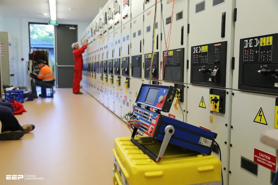
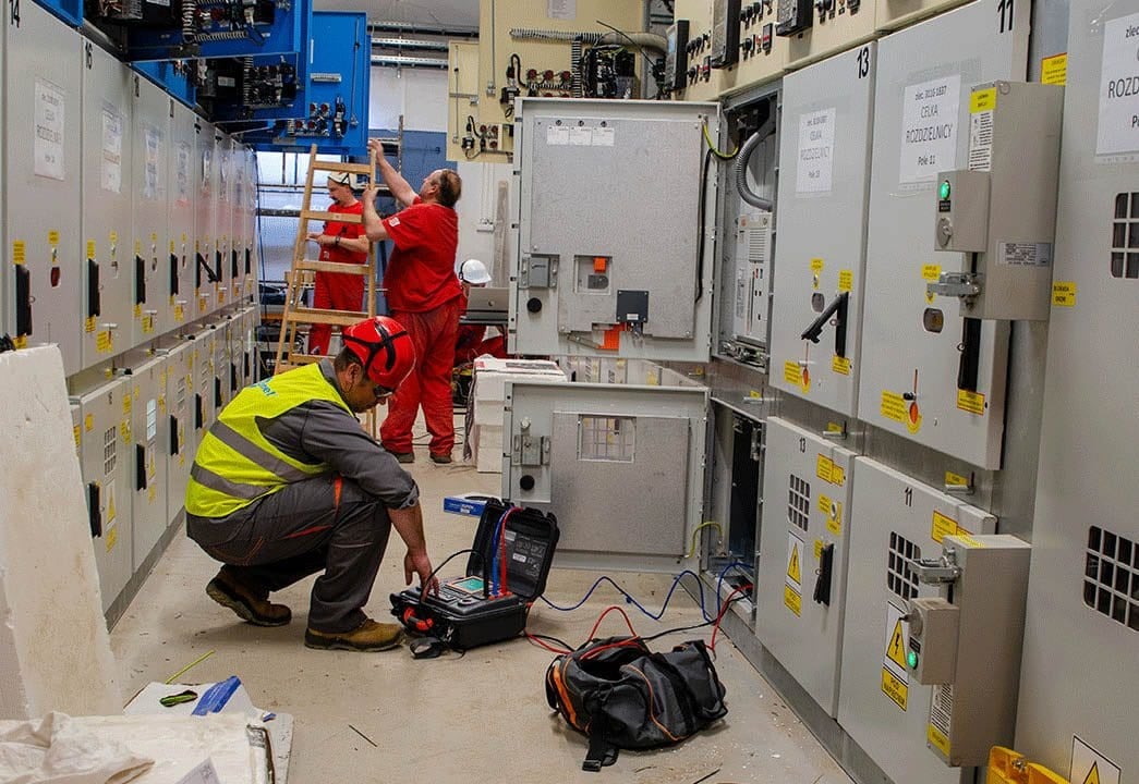
Figure 1 – Engineers performing testing of MV switchgear
Verification of test blocks and plugs in the CT circuit is another critical aspect of ensuring reliable operation. We will discuss the importance of periodically inspecting and verifying the test blocks and plugs used in the CT circuit. This verification process helps maintain the accuracy of CT measurements and reduces the chances of malfunctions or erroneous readings.
CT secondary circuit shorting and safety measures are essential for safe and efficient maintenance and testing procedures. We will explore the utilization of jumpers and shrouded test cable plugs to ensure proper shorting and safety during CT maintenance and testing activities. CT terminal block selection is a crucial decision that impacts the overall CT performance and system reliability.
We will conduct a comparative analysis of different practices for CT terminal block selection, highlighting the factors to consider when choosing the most suitable option for a specific application.
Additionally, we will discuss the wiring techniques of six-wires versus four-wires systems in CT installations. Understanding the differences and benefits of each wiring technique can help engineers and technicians make informed decisions and optimize the CT installation for accurate and reliable measurements.
The star point of the CT secondary side is an important consideration in system design and protection coordination. We will discuss the implications of different star point settings and provide examples of numerical relay configurations. Additionally, we will highlight the potential consequences of incorrectly selecting the star point, emphasizing the importance of accurate setting for optimal system
performance.
Finally, we will guide you through the process of performing VA burden tests on the CT secondary loop. We will explain the significance of VA burden
- Precautions for CT Shorting and Isolation: Safeguarding Against Indiscriminate Tripping and Ensuring Reliable Operation
- Understanding the Importance of Burden Testing for Current Transformers:
- Verification of Test Blocks & Plugs in the CT circuit
- CT Secondary Circuit Shorting and Safety Measures: Utilizing Jumpers and Shrouded Test Cable Plugs
- Exploring Different Practices for CT Terminal Block Selection: A Comparative Analysis
- CT Wiring Technique Six Wires vs Four Wires System
- Understanding CT Polarity and the Impact on Current Flow at the Secondary Side
- Significance of the Formation of Star Point at CT Secondary Wiring
- Star point Setting Example in Numerical Relays
- Impact of the Wrong Selection of Star Point in the Relays and Meters
- How to Perform VA Burden Test of CT Secondary Loop
1. Precautions for CT Shorting and Isolation
Safeguarding Against Indiscriminate Tripping and Ensuring Reliable Operation
When performing CT shorting and isolation, it is crucial to exercise utmost care, especially when the feeder is live or under load. The CT links are shortened one by one for each phase while adhering to a specific sequence. Let’s focus on the figure provided, where the red phase link is initially closed.
This indicates that the red phase current is bypassed, while the yellow and blue phase currents continue to flow towards the relay.
To understand the impact of shorting the CT links, it is important to consider the vector sum of current when all three phases are present. In this scenario, the vector sum is zero, indicating a balanced current flow. However, when one phase is missing due to the closure of a shorting link, the current in the neutral conductor becomes 1.73 times the phase current, assuming a balanced three-phase current.
By isolating these crucial signals, we ensure that the protection system remains unaffected by the CT shorting operation, enhancing the overall reliability and accuracy of the system. It is imperative to prioritize safety and follow these precautions to minimize risks and maintain the integrity of the protection scheme during CT shorting and isolation procedures.
Figure 2 – Illustration of CT shorting and isolating links in schematics
2. Understanding the Importance of Burden Testing for Current Transformers
To perform burden testing, it is essential to measure and analyze the impedance offered by all the components in the secondary loop. This includes the meter current coils, relay current coils, contact resistance, terminal blocks, wire resistance, and test switches. By quantifying the total burden, we can determine if it falls within the acceptable range for the CT.
By conducting thorough burden testing, we can ensure that the CT is supplying the expected current output accurately and reliably. This validation process helps maintain the integrity of the measurement and protection systems, reducing the risk of errors and ensuring the overall efficiency of the electrical system.
Figure 3 – Multi-core current transformer nameplate
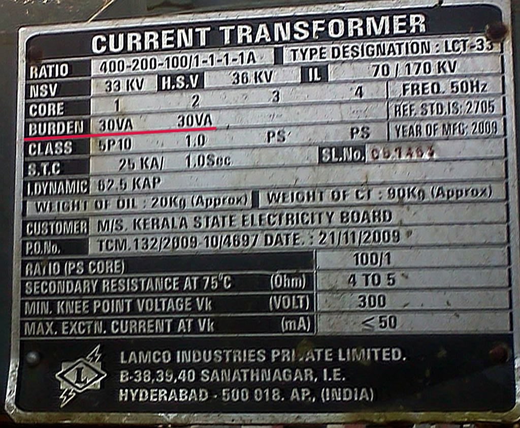
Burden testing plays a vital role in ensuring the proper functioning of current transformers. CTs secondary windings are connected with specific VA burden that need to be measured during commissioning of CT secondary loop. CTs are designed to provide the secondary output current based on their accuracy class.
Purpose of performing CT VA burden test yield following benefits:
- Connected burden measurement,
- Making sure that any CT secondary circuit is not remain opened by mistake,
- Making sure that any of the relay / meter current element / coil is not bypassed by shorting links, and
- Verifying any loose connection in CT circuit.
2.1 Connected Burden Measurement
One of the primary purposes of a CT VA burden test is to measure the connected burden accurately. By quantifying the burden, engineers can ensure that the CT is appropriately sized for the specific application. This measurement helps validate the CT’s capability to handle the expected load and guarantees accurate current measurements.
Related electrical guides & articles


Muhammad Kashif
Muhammad Kashif Shamshad is an Electrical Engineer and has more than 17 years of experience in operation & maintenance, erection, testing project management, consultancy, supervision, and commissioning of Power Plant, GIS, and AIS high voltage substations ranging up to 500 kV HVAC & ±660kV HVDC more than ten years experience is with Siemens Saudi Arabia.Profile: Muhammad Kashif
