
Estimated Study Time: 30 minutes
Transformer Specification
Power transformers are the backbone of modern electrical infrastructure, enabling the efficient transmission and distribution of electricity across vast networks. Given their critical role in maintaining grid stability and power quality, transformers must be designed, manufactured, and tested in accordance with globally recognized standards.
 Comprehensive Guide to Transformer Specification: Ensuring Compliance with IEC 60076
Among these, IEC 60076 – Power Transformers serves as the fundamental standard governing transformer specification, ensuring uniformity, reliability, and safety in transformer design and operation.
A well-prepared transformer specification is essential for defining operational requirements, ensuring compliance with industry standards, and optimizing transformer performance. It provides clarity on key electrical parameters, mechanical design, thermal performance, and environmental factors, thereby minimizing risks associated with performance inefficiencies and failures.
By adhering to IEC 60076, utilities, manufacturers, and system operators can ensure that transformers meet stringent technical and regulatory requirements while remaining cost-effective and energy-efficient.
Ambient temperature is another crucial factor influencing transformer performance, as excessive heat can degrade insulation and reduce operational lifespan. This article examines standard temperature limits, their impact on transformer efficiency, and strategies for mitigating thermal stress in extreme operating conditions.
Additionally, the role of cooling methods and temperature rise limits is analyzed, covering both oil-immersed and dry-type transformers, along with permissible temperature rise limits defined by IEC standards.
By understanding these foundational concepts, engineers, procurement specialists, and stakeholders can make informed decisions when specifying power transformers.
This Part 1 serves as the foundation for a more detailed exploration of advanced transformer specification considerations, which will be covered in Part 2 of this series.
- Understanding IEC 60076: The Global Standard for Power Transformers
- Key Considerations in Transformer Specification
- System Voltage and Power Rating Selection in Light of IEC 60076
- Ambient Temperature Considerations for Power Transformers
- Cooling Methods and Temperature Rise Limits in Power Transformers
- Temperature Rise Limits in Power Transformers
- Impact of Cooling and Temperature Rise on Transformer Performance
- Permissible Temperature Rise Limits for Oil-Immersed Transformers
- Permissible Temperature Rise Limits for Dry-Type Transformers
- BONUS (PDF) 🔗 Download “Modern and Conventional Methods for Transformer Condition Control”
1. Understanding IEC 60076: The Global Standard for Power Transformers
Power transformers play a critical role in electrical power systems, ensuring efficient voltage regulation and power distribution. To maintain consistency, reliability, and safety in transformer design and operation, the IEC 60076 standard provides a comprehensive framework covering all aspects of power transformer specifications.
IEC 60076 applies to power transformers with voltage ratings up to 765 kV, encompassing single-phase and three-phase transformers, auto transformers, and reactors.
It is applicable to both indoor and outdoor installations, covering diverse environmental and operational conditions.
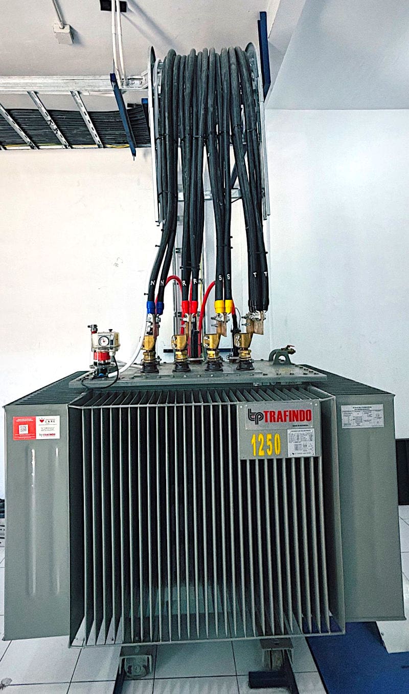
Figure 1 – Indoor oil-immersed sealed type transformer
1.1 Evolution and Global Adoption of IEC 60076
Originally introduced in 1953, the IEC 60076 standard has undergone multiple revisions to keep pace with advancements in transformer technology and power system requirements. The latest revision, published in 2020, reflects modern industry practices, improved materials, and updated testing methodologies.
Today, IEC 60076 is recognized and adopted in over 100 countries, reinforcing its position as a globally accepted standard for power transformers.
2. Key Considerations in Transformer Specification
The specification of a power transformer is a crucial step in ensuring its reliability, efficiency, and compliance with IEC 60076 and other relevant international standards. A well-prepared transformer specification outlines all necessary parameters to avoid operational inefficiencies, technical mismatches, and potential failures. Below are the key considerations that should be addressed when preparing a transformer specification.
One of the most critical aspects of transformer specification is defining rated power and voltage levels. The transformer must be specified with an appropriate power rating in MVA or kVA to ensure it can handle the expected load without excessive losses or overheating. The primary and secondary voltage levels must be clearly defined to match the system requirements.
This includes specifying whether the transformer will be used in transmission, distribution, or industrial applications and ensuring its voltage rating aligns with system design.
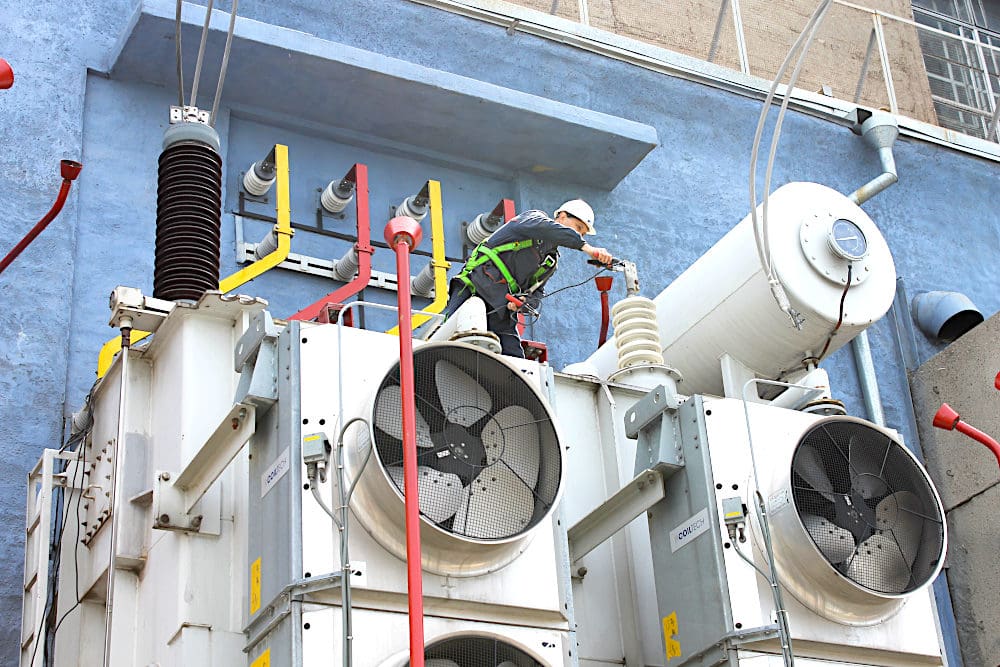
Another essential factor is insulation levels and dielectric strength, which determine the ability of the transformer to withstand over voltages, switching transients, and lightning impulses. The insulation coordination must be designed according to the highest voltage for equipment (Um) and basic insulation level (BIL) requirements, ensuring that the transformer operates safely under expected network conditions.
Figure 2 – Performing electrical insulation testing on transformer
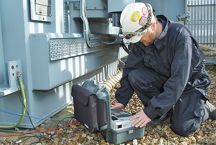
Proper selection of insulation materials and dielectric strength helps prevent insulation failures and extends transformer lifespan.
The transformer’s cooling method and temperature rise limitations must be specified to maintain safe operating conditions. Common cooling methods include ONAN (Oil Natural Air Natural), ONAF (Oil Natural Air Forced), OFAF (Oil Forced Air Forced), and OFWF (Oil Forced Water Forced), each suitable for different loading and environmental conditions.
Short-circuit strength and mechanical robustness are key considerations for ensuring the transformer can withstand electrical faults without structural or functional damage. The short-circuit impedance must be carefully specified to control fault currents and maintain system stability. A well-designed transformer must also be able to endure high mechanical stresses during faults, which requires robust winding and core construction.
Efficiency and losses are crucial factors in transformer selection. The specification must include no-load losses, load losses, and overall efficiency at different loading conditions. Since transformers operate continuously, minimizing energy losses can lead to significant cost savings over their lifespan.
Balancing initial capital cost with energy efficiency is a key decision in transformer procurement.
Figure 3 – Tranformer Automatic Voltage Regulator, type ‘TAPCON’
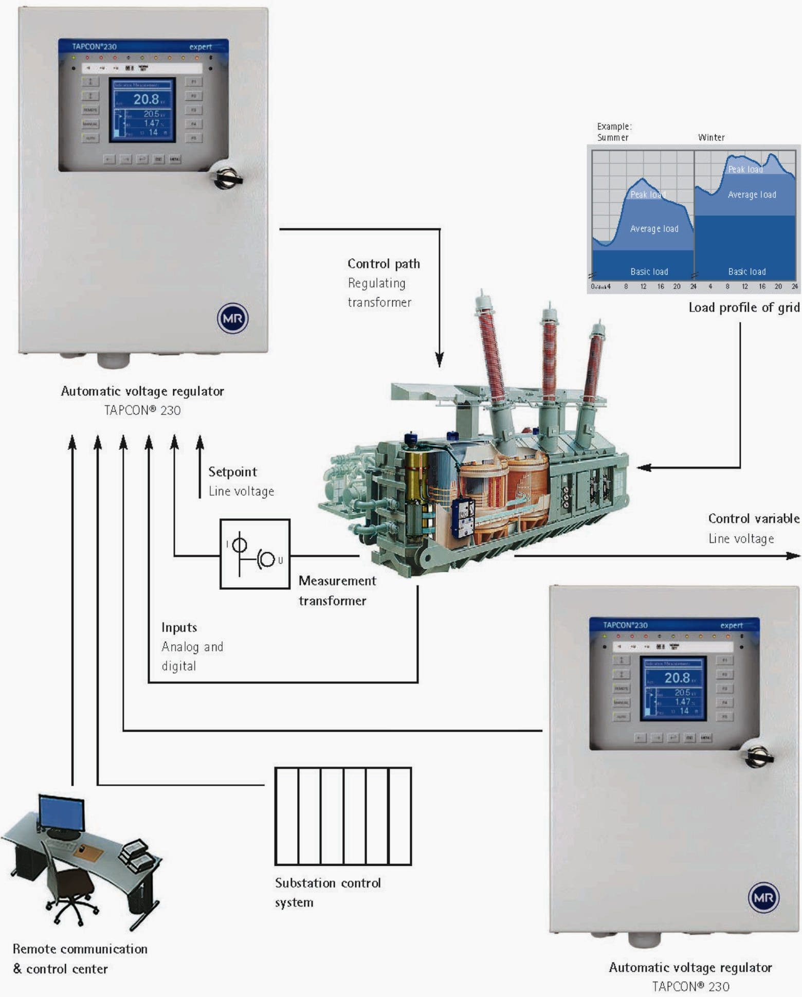
Voltage regulation and tapping arrangements should also be specified to ensure the transformer can adjust its output voltage based on network fluctuations. On-load tap changers (OLTC) and off-load tap changers (DETC) are used to regulate voltage within specified limits. The number of tapping steps, range of voltage adjustment, and type of tap changer must be clearly defined in the specification to maintain voltage stability.
Environmental and site conditions must be carefully considered in transformer specification.
Factors such as installation altitude, ambient temperature, humidity, pollution levels, and seismic activity directly impact transformer design and performance. Transformers intended for extreme conditions require additional design considerations, such as high-altitude insulation correction, corrosion-resistant materials, or enhanced cooling systems.
Ensuring compliance with these tests guarantees the quality, reliability, and safety of the transformer before deployment.
Suggested Guide – Power Transformers Testing Booklet For True Engineers
The transformer specification should also include rating plate and nameplate details, which provide essential information for identification, operation, and maintenance. The rating plate should include transformer type, rated power, primary and secondary voltages, connection symbol, cooling method, insulation class, impedance, and manufacturer details.
Transport, installation, and maintenance considerations must not be overlooked in transformer specification. Transformers are large and heavy equipment, requiring special handling, transportation, and installation procedures. The specification should define weight limitations, lifting arrangements, and storage conditions.
Additionally, guidelines for preventive maintenance, oil analysis, and periodic inspections should be outlined to ensure long-term reliability.
Further Study – Learn how to interpret transformer nameplate information
3. System Voltage and Power Rating Selection in Light of IEC 60076
The selection of system voltage and power rating for a transformer is one of the most critical aspects of its specification. Ensuring that the transformer operates within the appropriate voltage levels and power capacity is essential for its efficiency, reliability, and compliance with IEC 60076 – Power Transformers.
These parameters define the transformer’s capability to handle system loads, voltage fluctuations, and overall performance in an electrical network.
3.1 Voltage Rating Selection
The voltage rating of a transformer is determined by the system voltage and the operational requirements of the power network. According to IEC 60076-1, the transformer’s rated voltage (Ur) must be selected to match the highest voltage of the system to which it is connected, while considering insulation coordination and dielectric strength.
Highest Voltage for Equipment (Um)
IEC 60076 defines voltage ratings based on Um, which represents the maximum system voltage that the transformer must withstand under steady-state and transient conditions. The selection of Um ensures that the transformer’s insulation system is adequately rated to prevent dielectric breakdown.
Further Study – How to configure medium voltage switchgear: Key influences and stress variables
How to configure medium voltage switchgear: Key influences and stress variables
Rated Voltage (Ur)
The rated voltage of each winding of the transformer is assigned based on the primary and secondary system voltages. The standard defines preferred voltage ratings to facilitate compatibility with electrical grids and substation equipment.
Voltage Ratio
The voltage ratio is the relationship between the primary and secondary windings and must be selected based on the transformation requirements of the system. For example, a 132/11 kV transformer steps down the voltage from a transmission level to a distribution level.
The system voltage also influences the insulation coordination of the transformer, as per IEC 60076-3, which defines insulation levels and dielectric testing requirements for different voltage classes. Higher voltage transformers require stronger insulation and must withstand lightning impulse voltages and switching over voltages during system operations.
Suggested Course – Mastering Transformer Vector Groups: Learn How To Analyze and Draw Windings Connections
3.2 Power Rating Selection
The rated power (Sr) of a transformer is the amount of apparent power (in MVA or kVA) it can transfer between its windings under standard operating conditions. IEC 60076 provides guidelines on power rating selection based on system requirements, transformer loading conditions, and efficiency considerations.
Determination of Rated Power
IEC 60076-1 states that the rated power refers to continuous loading and is assigned to each winding of the transformer. In a two-winding transformer, the rated power is the same for both windings, while in a multi-winding transformer, different power ratings may apply to each winding.
Loading Cycle Considerations
The selection of rated power must consider the expected loading cycle, including normal, emergency, and short-term overload conditions.
Cooling Method and Power Rating Relationship
IEC 60076-2 specifies that transformers may have multiple assigned power ratings depending on their cooling method. For example, a transformer may have different power ratings for ONAN (Oil Natural Air Natural) and ONAF (Oil Natural Air Forced) cooling modes.
This ensures that transformers operate safely at varying load conditions without exceeding temperature rise limits.
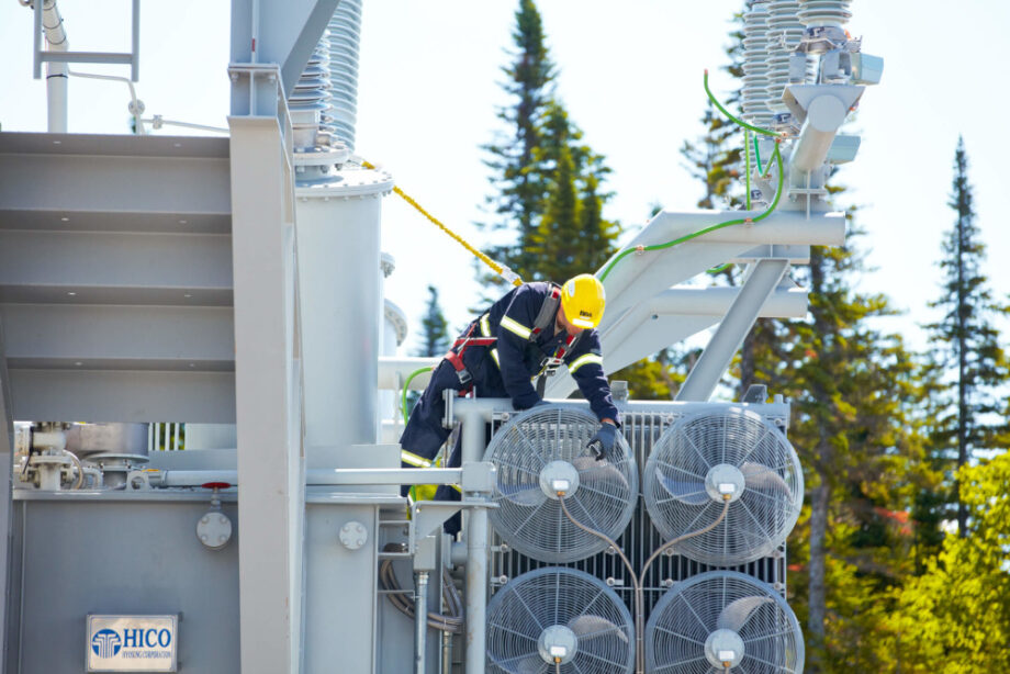
Figure 4 – Power transformer cooling fans
3.3 Factors Affecting Voltage and Power Rating Selection
Several factors influence the selection of system voltage and power rating, ensuring that the transformer performs reliably and efficiently:
1. Network Configuration and System Stability
The transformer must be compatible with the network voltage levels and short-circuit withstand capability. Higher voltage transformers require adequate insulation to manage transient overvoltages.
2. Load Growth and Future Expansion
Selecting an appropriate power rating must consider expected future demand increases. A transformer with an under-rated power capacity may lead to overloading, reduced efficiency, and premature failure.
3. Voltage Regulation and Tapping Requirements
If the transformer is expected to handle variations in system voltage, an On-Load Tap Changer (OLTC) or Off-Load Tap Changer (DETC) must be specified to maintain voltage stability. IEC 60076-1 provides recommendations for tapping range and step increments.
4. Short-Circuit Considerations
The transformer’s short-circuit impedance must be properly selected to limit fault currents while maintaining voltage stability. IEC 60076-5 outlines the short-circuit withstand capabilities of transformers based on system requirements.
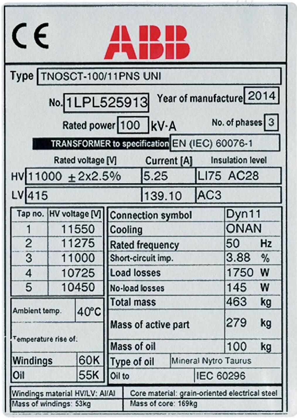
Figure 5 – 11/0.4kV 100kVA Transformer Nameplate
4. Ambient Temperature Considerations for Power Transformers
Ambient temperature is a critical factor in the design, operation, and performance of power transformers. Defined as the temperature of the surrounding air or cooling medium, it directly affects the thermal performance, insulation aging, and overall efficiency of the transformer.
IEC 60076-1 provides specific guidelines regarding the normal and extreme ambient temperature conditions under which power transformers must operate reliably.
4.1 Definition and Standard Limits
According to IEC 60076-1, the normal ambient temperature conditions for power transformers are:
- Maximum ambient temperature: +40°C
- Minimum ambient temperature: -25°C
- Average temperature over 24 hours: Not exceeding +35°C
For water-cooled transformers, the standard states that the temperature of the cooling water at the inlet should not exceed +25°C. However, in certain applications, transformers may be required to operate in unusual service conditions, such as extreme high or low temperatures, and additional design considerations must be made.
Further Study – Managing power transformers in service: The most important economic aspects
Managing power transformers in service: The most important economic aspects
4.2 Impact of Ambient Temperature on Transformer Performance
1. Thermal Stress and Insulation Life
The winding and core of a transformer generate heat during operation, and effective cooling is necessary to prevent excessive temperature rise. If the ambient temperature is high, the ability of the transformer to dissipate heat is reduced, leading to increased hot spot temperatures, accelerated insulation degradation, and a shorter operational lifespan.
IEC 60076-7 provides guidelines on thermal aging and how high temperatures can reduce insulation life.
2. Cooling System Performance
Transformers are designed with different cooling methods, such as ONAN, ONAF, OFAF, and OFWF. High ambient temperatures can reduce the effectiveness of these cooling systems, leading to higher oil and winding temperatures.
3. Transformer Load Capability
The rated power of a transformer is based on its ability to operate at standard ambient conditions. If the ambient temperature exceeds IEC-defined limits, the transformer’s loading capacity must be derated to prevent overheating. Conversely, in colder environments, transformers may be able to handle higher loads without exceeding their thermal limits.
4. Material Expansion and Contraction
Extreme temperature fluctuations can cause thermal expansion and contraction in transformer components, such as windings, insulation, and bushings. Over time, this thermal cycling can lead to mechanical stress, oil leaks, and structural weakening of transformer parts, particularly in outdoor installations exposed to direct sunlight or freezing conditions.
5. High-Altitude and Low-Temperature Considerations
At higher altitudes, where air density is lower, the cooling efficiency of air-cooled transformers decreases. IEC 60076-2 provides correction factors for transformers operating at altitudes above 1,000 meters, requiring enhanced cooling systems or derated load capacity to maintain safe operating temperatures.
In cold climates, special transformer designs may include low-temperature-resistant materials to prevent brittle failures and ensure reliable operation.
Further Study – How to prepare an enquiry for a power transformer: Design and tendering tips
How to prepare an enquiry for a power transformer: Design and tendering tips
4.3 Mitigation Strategies for Extreme Ambient Temperatures
To ensure transformer reliability in environments with extreme ambient temperatures, several mitigation strategies can be applied:
1. Enhanced Cooling Systems
Using forced-air or forced-oil cooling systems (ONAF, OFAF) can improve heat dissipation in high-temperature environments.
2. Oil Type Selection
In extremely cold conditions, special low-viscosity transformer oils can be used to maintain proper fluid circulation and prevent gelling.
3. Proper Ventilation and Shading
In hot climates, transformers should be installed in well-ventilated areas or provided with shading to reduce heat buildup.
Thermal Insulation and Heaters
In freezing environments, anti-condensation heaters and insulation jackets can prevent moisture buildup and maintain operational temperature.
Figure 6 – Transformer oil is frequently used in electrical devices as a coolant, insulator, and arc-suppressor. Aromatic hydrocarbons, paraffins, and naphthenes are all components of transformer oil.

5. Cooling Methods and Temperature Rise Limits in Power Transformers
Cooling is a critical factor in transformer design and operation, as excessive temperatures can lead to insulation degradation, reduced lifespan, and operational failures. IEC 60076-2 provides detailed guidelines on acceptable temperature rise limits and defines various cooling methods to ensure transformers operate within safe thermal limits.
5.1 Cooling Methods in Power Transformers
Power transformers generate heat due to iron losses (core losses) and copper losses (winding losses). To maintain thermal stability, different cooling techniques are used based on transformer size, load conditions, and environmental factors.
IEC 60076-2 classifies transformer cooling methods into the following main types:
5.1.1 Oil-Immersed Transformer Cooling Methods
Oil-immersed transformers use insulating mineral oil or synthetic insulating liquids to transfer heat from windings and the core to the tank surface, where it is dissipated into the surrounding air.
The cooling methods are classified as follows:
ONAN – Oil Natural Air Natural
- Oil circulates naturally by convection.
- Heat is transferred from the windings to the oil, then to the transformer tank, and finally dissipated into the air.
- Used in small to medium-sized transformers where natural cooling is sufficient.
ONAF – Oil Natural Air Forced
- Similar to ONAN, but fans are used to increase airflow over the transformer tank to enhance cooling.
- Allows for higher loading without exceeding temperature limits.
- Commonly used in medium to large power transformers.
OFAF – Oil Forced Air Forced
- Uses oil pumps to circulate oil through cooling radiators, with fans forcing air over the radiators for improved heat dissipation.
- More efficient than ONAF and suitable for large power transformers where natural circulation is insufficient.
OFWF – Oil Forced Water Forced
- Uses oil pumps to circulate oil through heat exchangers, where the heat is transferred to a forced water-cooling system.
- Ideal for very large transformers or installations in confined spaces, such as underground substations or power plants.
ODWF – Oil Directed Water Forced
- Similar to OFWF but uses directed oil flow over windings to ensure better heat dissipation.
- Used in high-capacity transformers requiring precise temperature control.
Watch Lesson – Transformer contruction and cooling
5.1.2 Dry-Type Transformer Cooling Methods
Dry-type transformers do not use liquid insulation and rely on air as the cooling medium. These transformers are generally used in indoor, fire-prone, or environmentally sensitive areas. The main cooling types include:
AN – Air Natural
Heat dissipates through natural air convection. Used in small dry-type transformers.
AF – Air Forced
Cooling is enhanced by fans, improving heat dissipation for medium-to-large dry-type transformers.
AFWF – Air Forced Water Forced
A water-cooled heat exchanger is used for high-power applications where natural air cooling is insufficient.
Recommended Course – Fundamentals of Three-Phase Electrical Transformers
6. Temperature Rise Limits in Power Transformers
Temperature rise refers to the difference between the transformer’s operating temperature and the ambient temperature. IEC 60076-2 specifies the allowable temperature rise limits to ensure safe operation and prevent insulation degradation.
The temperature rise limits depend on the insulation class and cooling method.
6.1 Winding Temperature Rise Limits
For Oil-immersed transformers: Maximum winding temperature rise: 65°C
For Dry-type transformers:
- Class A insulation: 60°C
- Class B insulation: 80°C
- Class F insulation: 100°C
- Class H insulation: 125°C
The winding temperature rise is measured using resistance methods, ensuring it remains within safe limits under rated load conditions.
Figure 7 – Transformer winding and oil temperature indicators

6.2 Top Oil Temperature Rise Limits (For Oil-Immersed Transformers)
- ONAN, ONAF, OFAF transformers: Maximum 55°C rise above ambient.
- OFWF, ODWF transformers: Maximum 50°C rise above ambient.
6.3 Hot-Spot Temperature Limits
Hot-spot temperatures refer to the maximum temperature in the most thermally stressed part of the winding. IEC standards specify:
- Maximum winding hot-spot temperature: 98°C for oil-immersed transformers.
- Maximum winding hot-spot temperature for dry-type transformers: Varying based on insulation class.
7. Impact of Cooling and Temperature Rise on Transformer Performance
1. Aging and Insulation Degradation
Higher temperatures accelerate insulation degradation, reducing transformer lifespan. IEC 60076-7 states that every 10°C rise in temperature halves insulation life.
2. Load Capacity and Efficiency
Transformers operating at high temperatures must be derated to prevent overheating. Efficient cooling methods allow transformers to handle higher loads without exceeding thermal limits.
3. Operational Safety
Exceeding temperature rise limits can lead to thermal runaway, insulation failure, and transformer breakdowns. Proper cooling design prevents excessive heat accumulation.
4. Environmental Considerations
In areas with high ambient temperatures, enhanced cooling systems (ONAF, OFAF, or water-cooled systems) are necessary to maintain safe operating conditions.
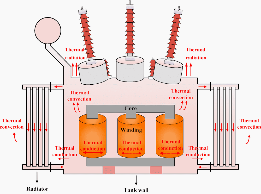
Figure 8 – Cooling conventions in oil immersed transformer
8. Permissible Temperature Rise Limits for Oil-Immersed Transformers
According to IEC 60076-2, the maximum temperature rise for different transformer components is:
Table 1 – Maximum temperature rise for different transformer components
| Component | Maximum Temperature Rise Over Ambient |
| Top Oil Temperature (ONAN, ONAF, OFAF, etc.) | 60 K |
| Winding Temperature Rise | 65 K |
| Hot-spot Temperature Rise | 78 K |
Where:
- The top oil temperature rise refers to the temperature difference between the hottest point in the oil and ambient air.
- The winding temperature rise is the difference between the hottest winding conductor and ambient air.
- The hot-spot temperature rise is the maximum local temperature inside the winding insulation, crucial for insulation aging.
9. Permissible Temperature Rise Limits for Dry-Type Transformers
For dry-type transformers, IEC 60076-11 defines temperature limits based on the insulation class of the windings.
Table 2 – Temperature limits based on the insulation class of the windings
| Insulation Class | Maximum Winding Temperature (°C) | Maximum Temperature Rise (K) |
| Class A | 105°C | 60 K |
| Class B | 130°C | 80 K |
| Class F | 155°C | 100 K |
| Class H | 180°C | 125 K |
The higher the insulation class, the greater the permissible temperature before insulation deterioration occurs.
10. BONUS (PDF): Modern and Conventional Methods for Transformer Condition Control
Download: Modern and Conventional Methods for Transformer Condition Control (for premium members only):
Related electrical guides & articles


Muhammad Kashif
Muhammad Kashif Shamshad is an Electrical Engineer and has more than 17 years of experience in operation & maintenance, erection, testing project management, consultancy, supervision, and commissioning of Power Plant, GIS, and AIS high voltage substations ranging up to 500 kV HVAC & ±660kV HVDC more than ten years experience is with Siemens Saudi Arabia.Profile: Muhammad Kashif

Wish to receive this article by email
Hi Bashir,
You can subscribe and receive newsletter with all EEP’s notifications here:
https://www.subscribepage.com/eep-weekly-digest