
Estimated Study Time: 32 minutes
Voltage Transformer Supervision
Voltage transformer supervision, often referred to as VT fuse fail supervision relay, plays a pivotal role in safeguarding electrical systems. Its primary objective is to detect any potential failure within the voltage transformer (VT) circuit. This raises the important question: why is it essential to monitor VT circuits, and what could be the consequences if we fail to detect issues within the VT secondary circuit?
 A comprehensive guide to voltage transformer (VT) circuit supervision techniques
Modern electrical systems utilize miniature circuit breakers (MCBs) for the protection of VT circuits, while historically, fuses were employed for this purpose. MCBs and fuses serve to provide shortcircuit protection at the VT secondary winding, effectively disconnecting the VT supply in the event of a fault.
Now, let’s consider a scenario where a VT secondary is linked to an under-voltage protection system, and the VT MCB trips or the VT fuse blows. In such a situation, the under-voltage protection mechanism cannot distinguish between a genuine under-voltage condition and a VT MCB trip.
This shift in impedance, due to the fault, moves from the load impedance to the line impedance at a specific line angle. The relay now perceives an impedance within its protection zones and promptly issues a trip command to isolate the fault.
Figure 1 – Distance Relay load Impedance, line impedance and fault impedance (as seen by the distance relay)
However, imagine a scenario where the distance relay observes the load impedance, and the power system is operating stably. In this case, a fault occurs in the VT secondary circuit, causing the VT MCB to trip, leading to zero voltage supplied to the distance relay. Consequently, the relay calculates the impedance as zero and wrongly identifies it as a fault, issuing an unnecessary trip command.
In such instances where the system is perfectly healthy and no actual fault exists, the unnecessary tripping can be problematic. Therefore, there arises a need to implement additional protection measures that can prevent the distance relay from tripping when the VT trips, the VT MCB opens, or a fault occurs in the VT circuit.
This article will delve into the various techniques employed for VT circuit supervision, encompassing both hardware logic and software-based VT failure supervision schemes.
These techniques are pivotal in ensuring the reliability and stability of electrical systems by preventing erroneous tripping and accurately detecting genuine faults within the VT circuit.
- About Voltage Transformer (VT) in a Few Words
- VT Secondary Distribution
- Enhancing Voltage Transformer Secondary Circuit Protection: Fuses vs. MCBs in Substations
- Conventional VT Supervision Techniques:
- VT MCB Trip Supervision function:
- VT Fuse Fail Relays:
- Numerical Relay Fuse Fail/VT Failure Functions:
- Measuring Voltage Failure and Its Impact
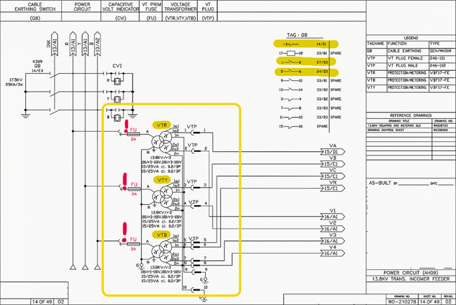
- BONUS (PDFs): Wiring Diagrams of 13.8 kV Transformer Incomer Feeder and 132/11.5 kV GIS Substation SLD
1. About Voltage Transformer (VT)
VT Configuration
A voltage transformer (VT) is an essential device employed in substations to efficiently lower high voltage (HV) levels to a more manageable and safe voltage range suitable for connection to various protection relays, measurement instruments, and control devices. These components are pivotal for maintaining the integrity and operational control of the substation.
Voltage transformers come in different configurations, which can include both single-core and multicore designs. In the case of multi-core VTs, each serving a specific purpose within the substation’s electrical system.
Meanwhile, the other core or cores of the VT can be linked to metering devices. These metering devices are responsible for precisely measuring the electrical parameters, such as voltage and current, which are crucial for billing, monitoring power quality, and conducting various analyses of the electrical system’s performance.
Figure 2 – A voltage transformer with multiple cores is depicted in the relay and metering diagram

2. VT Secondary Distribution
A Voltage Transformer (VT) comprises both High Voltage (HV) and Low Voltage (LV) windings. In practice, the LV side of a VT often operates at standard voltages like 110V or 100V. The secondary side of a VT can be branched out to various devices, but it is essential to ensure that the collective electrical load, known as the “burden”, connected to the VT does not exceed or surpass the rated burden capacity of the VT.
The VT’s secondary winding serves as the primary point of connection within the VT junction box. This is where all the individual VT cores are interconnected. It is considered good practice to incorporate Miniature Circuit Breakers (MCBs) or fuses directly at the VT junction box.
However, when operating at medium voltage levels, VT MCBs are typically installed within the Low Voltage (LV) panel.
This protective measure ensures that each branch of the electrical system connected to the VT remains safeguarded in case of any electrical faults, thereby preventing potential damage to equipment and ensuring the overall reliability of the electrical distribution network.
Figure 3 – VT Secondary circuit distribution
3. Enhancing Voltage Transformer Secondary Circuit Protection
Fuses vs. MCBs in Substations
Our primary objective is to safeguard the Voltage Transformer (VT) secondary circuit from potential short-circuits that could cause harm to the VT secondary windings. To achieve this, two different protective devices, namely fuses and Miniature Circuit Breakers (MCBs), have been employed.
In my practical experience in the field, I have observed that older substations commonly utilized fuses for this purpose. However, there has been a noticeable shift in recent times towards the prevalent use of MCBs.
Related electrical guides & articles


Muhammad Kashif
Muhammad Kashif Shamshad is an Electrical Engineer and has more than 17 years of experience in operation & maintenance, erection, testing project management, consultancy, supervision, and commissioning of Power Plant, GIS, and AIS high voltage substations ranging up to 500 kV HVAC & ±660kV HVDC more than ten years experience is with Siemens Saudi Arabia.Profile: Muhammad Kashif
