
Estimated Study Time: 31 minutes
Earthing Tips and Facts
In the world of electrical engineering, ensuring the safety and reliability of power systems is paramount. A critical aspect of this is the proper implementation of earthing and bonding systems. This article delves into the fundamental concepts and applications of earthing and bonding, with a focus on their importance in maintaining safety and system integrity in electrical installations.
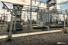
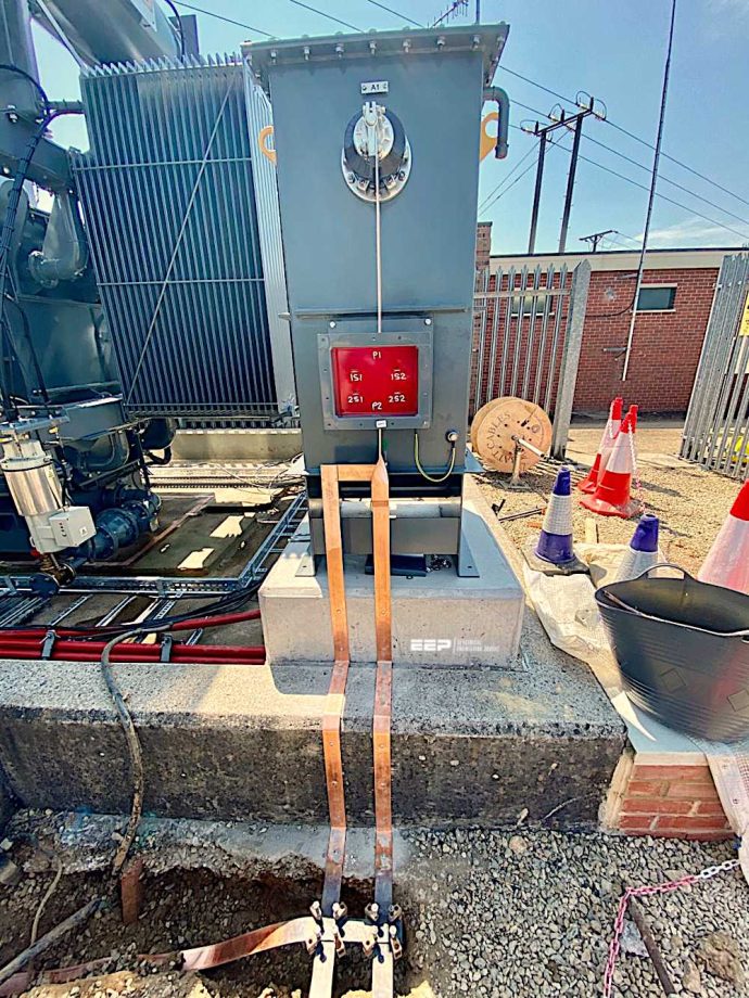 Handy earthing guidelines for true engineers (on photo: Earthing via copper brazing of earth tapes for 33kV power transformer)
Earthing, or grounding, is a crucial safety measure designed to protect both people and equipment from electrical faults. It involves creating a direct physical connection between the electrical system and the ground, which helps in preventing electrical shock and ensuring the safe operation of electrical equipment.
Protective earthing is examined to understand its role in enhancing safety by diverting fault currents away from users and equipment. The importance of earthing is underscored through its various applications and the procedures involved in implementing temporary earthing measures when needed.
The concept of bonding is introduced next, defining its purpose and significance in electrical systems. Different types of bonding and their implementation are discussed, along with regulatory standards that guide their use. Practical examples illustrate the application of bonding in real-world scenarios.
Finally, the discussion extends to the substation earth mesh, a key component in the design and operation of substations. The purpose, function, and design considerations of substation earth meshes are detailed, along with an examination of their components and practical examples of their implementation.
By comprehensively addressing these topics, this article aims to provide a thorough understanding of earthing and bonding principles and their application in ensuring electrical safety and system reliability.
- What is Earthing?
- Types of Earthing:
- Protective Earthing Mechanism:
- Temporary Earthing:
- Bonding:
- Equipotential Earthing Mats:
- Substation Earth Mesh:
- BONUS (PDF) 🔗 Download Grounding Installation Practices for Power Systems
1. What is Earthing?
Earthing, also known as grounding, is a fundamental safety measure in electrical engineering. It involves connecting the metallic parts of electrical equipment to the earth, creating a path for fault currents to flow safely into the ground.
This connection helps protect both people and equipment from electric shocks and damage due to electrical faults.
2. Types of Earthing
2.1 System Earthing
System earthing refers to the grounding of the power system’s neutral point. This type of earthing ensures the stability and safety of the entire electrical system. By grounding the neutral point, any faults that occur in the system can be safely dissipated into the earth, minimizing the risk of electric shock and equipment damage.
Key aspects of system earthing include:
- Neutral Earthing: Connecting the neutral point of a transformer or generator to the ground.
- Solid Earthing: Directly connecting the neutral point to the earth without any impedance.
- Resistance Earthing: Using a resistor between the neutral point and the ground to limit fault currents.
- Reactance Earthing: Using a reactance (inductor) to ground the neutral point, controlling fault currents and limiting voltage rise.
Further Study – Earthing In a Nutshell (Classification, Isolated Neutral, Methods Of Neutral Grounding)
Earthing In a Nutshell (Classification, Isolated Neutral, Methods Of Neutral Grounding)
2.2 Functional Earthing
Functional earthing involves grounding certain parts of an electrical installation to ensure proper operation of the electrical system. This type of earthing is essential for the correct functioning of electronic equipment and systems.
Key aspects of functional earthing include the following:
Key Aspect #1 – Operational Stability
Ensuring stable operation of sensitive equipment by providing a reference voltage level.
Key Aspect #2 – EMI/RFI Protection
Reducing electromagnetic interference (EMI) and radio frequency interference (RFI) by grounding shielding and other components.
Key Aspect #3 – Signal Integrity
Maintaining the integrity of communication and control signals in complex electrical systems.
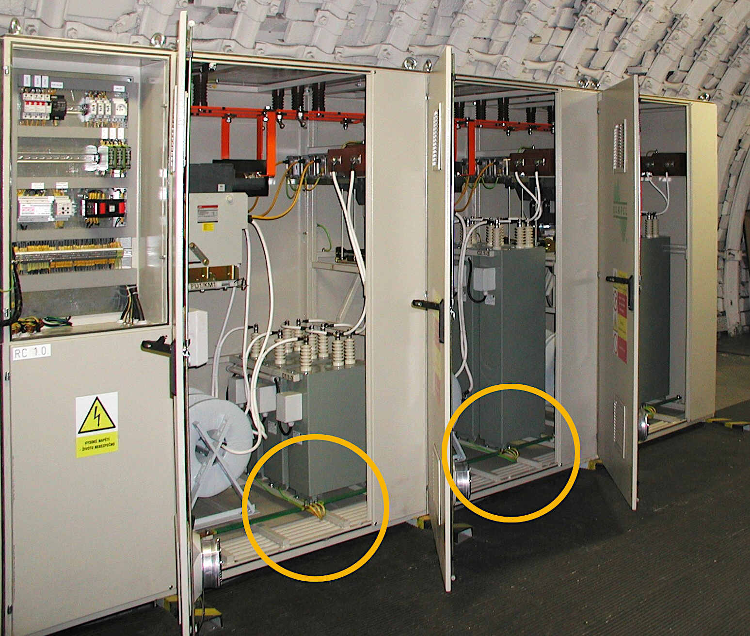
Figure 1 – An example of earthing of capacitor bank
2.3 Protective Earthing
Protective earthing is a safety measure that connects the non-current-carrying metal parts of electrical equipment to the ground. The primary purpose is to protect people from electric shocks and prevent electrical fires by ensuring that any fault current flows directly to the earth.
Key aspects of protective earthing include:
Key Aspect #1 – Safety
Protects against electric shocks by providing a path for fault currents to flow into the ground.
Key Aspect #2 – Fault Current Path
Ensures that if a live wire touches a metal part of the equipment, the current will flow to the ground rather than through a person.
Key Aspect #3 – Equipment Protection
Prevents damage to equipment by safely dissipating fault currents.
Key Aspect #4 – Compliance
Meets electrical safety regulations and standards, ensuring that electrical installations are safe for use.
Figure 2 – Example of protective earthing & human safety
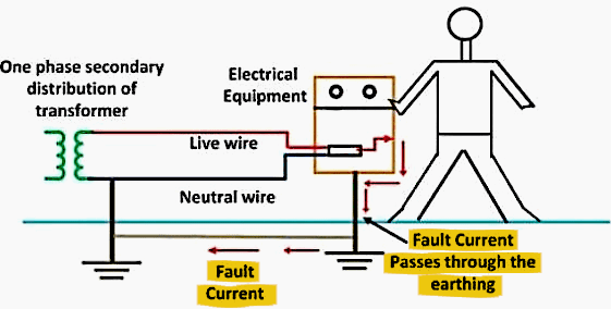
2.4 Protective Earthing Explained
The Figure 2 illustrates the concept of protective earthing, where the metallic body of electrical equipment is grounded. This is a crucial safety measure because the metallic body, although non-current carrying, can become a hazard if a fault occurs.
Scenario Description:
Scenario #1 – Metallic Enclosure Grounding
The body of the electrical equipment, which is metallic and does not normally carry current, is connected to the ground.
Scenario #2 – Insulation Failure
Imagine the insulation of the phase wire is damaged, causing the phase conductor to come into direct contact with the metallic enclosure.
Scenario #3 – Enclosure Becoming Live
In this situation, the enclosure will become live, taking on the same potential as the phase voltage, posing a serious electric shock hazard.
Scenario #4 – Grounded Equipment
If the equipment is properly grounded, the fault current will flow through the ground connection rather than through a person who might touch the enclosure.
Scenario #5 – Fault Current Path and MCB Operation
- The fault current will follow the path of least resistance. Since the enclosure is grounded, this path will be through the ground wire.
- The high fault current will be detected by a protective device, such as a Miniature Circuit Breaker (MCB). The MCB will trip, isolating the power supply and preventing further danger.
Scenario #5 – Ensuring Safety
If a person touches the panel, the current will flow through the low-resistance ground connection rather than through the person’s body. This significantly reduces the risk of electric shock, ensuring the person’s safety.
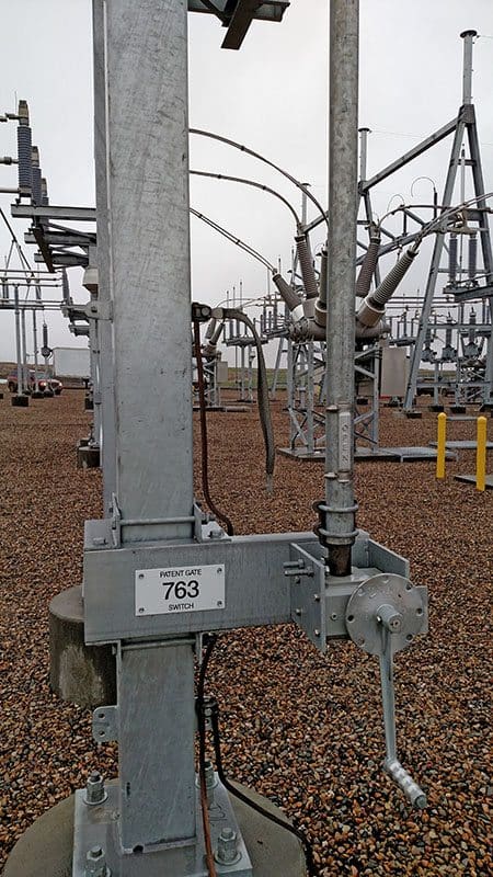
Figure 3 – 144kV Lightning Arresters with grounded bottom terminals and with insulated leads
3. Protective Earthing Mechanism
Normal Condition: Under normal operating conditions, the metallic body of the electrical equipment is at earth potential (0 volts) because it is connected to the ground.
Fault Condition: When the insulation of a live conductor fails, and the live conductor contacts the metallic enclosure, the enclosure becomes live.
Ground Connection: The ground connection ensures that the fault current has a low-resistance path to earth. This path is crucial for the rapid detection and isolation of the fault by protective devices like MCBs.
Related electrical guides & articles


Muhammad Kashif
Muhammad Kashif Shamshad is an Electrical Engineer and has more than 17 years of experience in operation & maintenance, erection, testing project management, consultancy, supervision, and commissioning of Power Plant, GIS, and AIS high voltage substations ranging up to 500 kV HVAC & ±660kV HVDC more than ten years experience is with Siemens Saudi Arabia.Profile: Muhammad Kashif
