
Estimated Study Time: 12 minutes
Substation control system
To form a substation control system, the various elements described above must be assembled into some form of topology. Three major hardware topologies can be identified as being commonly used.
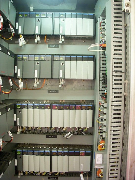
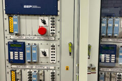
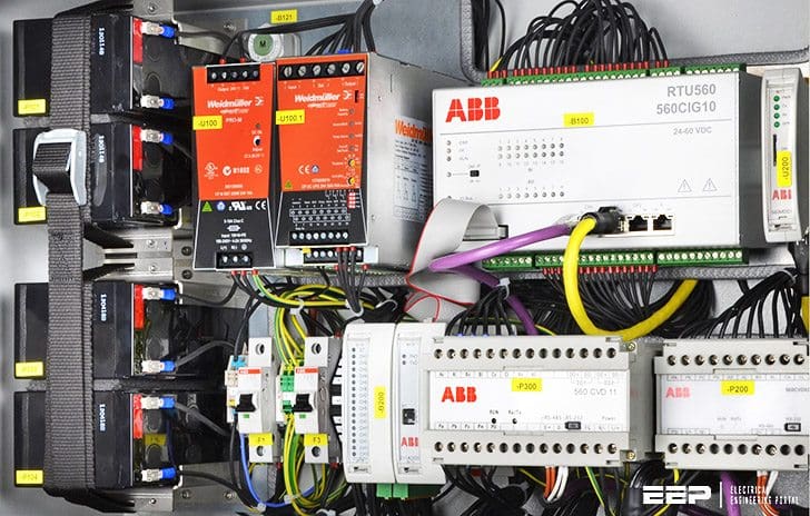 Hardware Implementation of Substation Control and Automation (on photo: Grid automation technology - FIONA - Flexible intelligent local network automation; credit: ABB)
Let’s get into details of each of hardware topologies:
HMI based Topology
This takes the form of Figure 1. The software to implement the substation control and automation functions resides in the HMI computer and this has direct links to IED’s using one or more communications protocols.
The link to a remote SCADA system is normally also provided in the HMI computer, though a separate interface unit may be provided to offload some of the processor requirements from the HMI computer, especially if a proprietary communications protocol to the SCADA system is used.
For this topology, a powerful HMI computer is clearly required if large numbers of IED’s are to be accommodated.
In practice, costs usually dictate the use of a standard PC, and hence there will be limitations on substation size that it can be applied to because of a resulting limit to the number of IED’s that can be connected.
The other important issue is one of reliability and availability – there is only one computer that can control the substation and therefore only local manual control will be possible if the computer fails for any reason.
Such a topology is therefore only suited to small MV substations where the consequences of computer failure (requiring a visit from a repair crew to remedy) are acceptable. Bay Modules are not used, the software for control and interlocking of each substation bay runs as part of the HMI computer software.
Go back to Hardware Topologies ↑
RTU based Topology
This topology is an enhancement of the HMI topology and is shown in Figure 2. A microprocessor based RTU is used to host the automation software, freeing the HMI computer for operator interface duties only.
The HMI computer can therefore be less powerful and usually takes the form of a standard PC, or for not-normally manned substations, visiting personnel can use a portable PC.
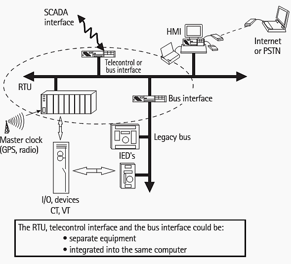
The RTU is purpose designed and can house one or more powerful microprocessors. A greater number of I/O points can be accommodated than in the HMI topology, while the possibility exists of hosting a wider variety of communication protocols for IED’s and the remote SCADA connection.
Bay Modules are not required, the associated software for interlocking and control sequences is part of the RTU software.
Go back to Hardware Topologies ↑
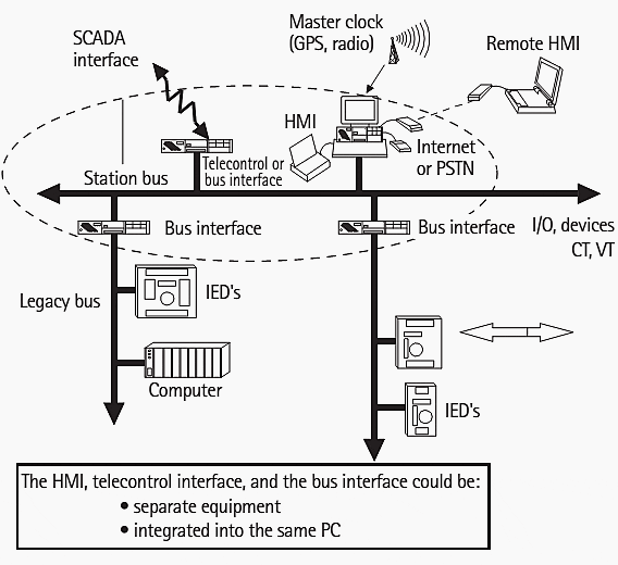
Decentralised Topology
This topology is illustrated in Figure 3. In it, each bay of the substation is controlled by a Bay Module, which houses the control and interlocking software, interfaces to the various IED’s required as part of the control and protection for the bay, and an interface to the HMI.
The amount of data from the various substation I/O points dictates that a separate SCADA interface unit is provided (often called an RTU or Gateway), while it is possible to have more than one HMI computer, the primary one being dedicated to operations and others for engineering use.
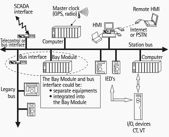
Optionally, a remote HMI computer may be made available via a separate link. It is always desirable in such schemes to separate the realtime operations function from engineering tasks, which do not have the same time-critical importance.
The connection between the various Bay Modules and the HMI computer is of some interest.
Simplest is the star arrangement of Figure 4(a). This is the least-cost solution, but suffers from two disadvantages. Firstly, a break in the link will result in loss of remote control of the bay affected; only local control via a local HMI computer connected to the bay is then possible.
Secondly, the number of communication ports available on the HMI computer will limit the number of Bay Modules.
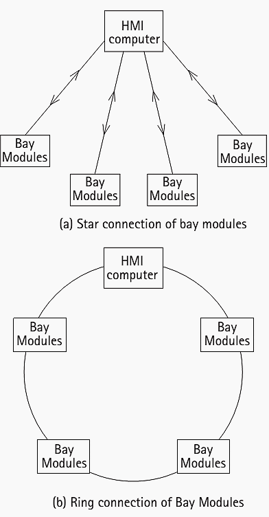
Of course, it is possible to overcome the first problem by duplicating links and running the links in physically separate routes. However, this makes the I/O port problem worse, while additional design effort is required in ensuring cable route diversity.
An alternative is to connect the Bay Modules, HMI computer and SCADA gateway in a ring, as shown in Figure 4(b).
The detection of ring breakage and re-configuration required can be made automatically. Thus, the availability and fault tolerance of the network is improved. Multiple rings emanating from the HMI computer can be used if the number of devices exceeds the limit for a single ring. It can be easier to install on a step-by-step basis for retrofit applications, but of course, all these advantages have a downside.
The cost of such a topology is higher than that of the other solutions, so this topology is reserved for situations where the highest reliability and availability is required – i.e. HV and EHV transmission substations.
Redundancy can also be provided at the individual device level. Relays and other IED’s may be duplicated, though this would not be usual unless required for other reasons (e.g. EHV transmission lines may be required to have duplicate main protections – this is not strictly speaking duplication of individual devices – which would require each individual main protection to have two identical relays voting on a ‘1 out of 2’ basis).
The total I/O count in a major substation will become large and it must be ensured that the computer hardware and communication links have sufficient performance to ensure prompt processing of incoming data.
Overload in this area can lead to one or more of the following:
- Undue delay in updating the system status diagrams/events log/alarm log in response to an incident
- Corruption of system database, so that the information presented to the operator is not an accurate representation of the state of the actual electrical system
- System lockup
As I/O at the bay level, both digital and analogue will typically be handled by intelligent relays or specialised IED’s, it is therefore important to ensure that these devices have sufficient I/O capacity. If additional IED’s have to be provided solely for ensuring adequate I/O capacity, cost and space requirements will increase.
There will also be an increase in the number of communication links required.
A practical specification for system response times is given in Table 1. Table 2 gives a typical specification for the maximum I/O capacities of a substation automation system.
Table 1 – Practical system response times for a substation automation scheme
| Signal Type | Response Time to/from HMI |
| Digital Input | 1s |
| Analogue Input | 1s |
| Digital Output | 0.75s |
| Disturbance Record File | 3s |
Table 2 – Typical I/O capacities for a substation automation system
| I/O Type | Capacity |
| Digital Input | 8196 |
| Digital Output | 2048 |
| Analogue Input | 2048 |
| Analogue Output | 512 |
A significant problem to be overcome in the implementation of communication links is the possibility of electromagnetic interference. The low voltage levels that are used on most types of communication link may be prone to interference as a result.
Care over the arrangement of the communication cables is also required. It may also help to use a communication protocol that incorporates a means of error detection and/or correction. While it may not be possible to correct all errors, detection offers the opportunity to request re-transmission of the message, and also for statistics to be gathered on error rates on various parts of the system.
An unusually high error rate on a part of the communication system can be flagged to maintenance crews for investigation.
Go back to Hardware Topologies ↑
Reference // Network Protection and Automation Guide – Areva
Related electrical guides & articles


Edvard Csanyi
Hi, I'm an electrical engineer, programmer and founder of EEP - Electrical Engineering Portal. I worked twelve years at Schneider Electric in the position of technical support for low- and medium-voltage projects and the design of busbar trunking systems.I'm highly specialized in the design of LV/MV switchgear and low-voltage, high-power busbar trunking (<6300A) in substations, commercial buildings and industry facilities. I'm also a professional in AutoCAD programming.
Profile: Edvard Csanyi

Dear Edvard very Useful information in you every Articles Learn a lot .Thanks for sharing the Knowledge.
Ogale Eleme Rivers State, Nigeria
Edvard csanyi
I’m a Nigerian. I’ve seen some of your designs and really they are products of great ingeniouty. Do you over online training on substation monitoring and control?
I read and I learn. Thanks Edvard for sharing.
A good system of control, knowledge and planning
Very incisive article. Please keep us updated. Thanks.
I always read Edvard’s EEP articles and I am very much impressed with his systematic and simple approach to Electrical Engineering topices.
Please continue your portal as it is a very important platform for all of us. So is Edvard, very important to us.