
Estimated Study Time: 5 minutes
Measures to eliminate harmonic currents
A number of measures can be taken to eliminate or reduce the effects of harmonic currents in the neutral conductor, in particular third harmonic currents. Let’s talk about the following five measures: modifications to the installation, star-delta transformer, transformer with zigzag secondary, reactance with zigzag connection and third order filter in the neutral.
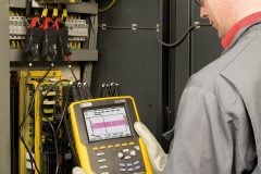
 How to manage harmonic currents affecting the neutral (photo credit: Edvard Csanyi)
- Modifications to the installation
- Star-delta transformer
- Transformer with zigzag secondary
- Reactance with zigzag connection
- Third order filter in the neutral
1. Modifications to the installation
The most common solutions for avoiding neutral conductor overload are as follows //
You can use a separate neutral conductor for each phase. This solution is rarely used because it is expensive.
Better solution is to double the neutral conductor. As the current in the neutral cannot exceed 1.73 times the current in each phase, this is an easy solution to implement in existing systems.
Or, another way is to use trunking with ratings suitable for the current in the neutral, which may be the dominant current.
2. Star-delta transformer
This configuration is used frequently in electrical distribution in order to eliminate the circulation of third harmonic currents in distribution and transmission networks.
3. Transformer with zigzag secondary
This configuration with zigzag secondary is also used in distribution and can have the same effect as the star-delta transformer configuration.
Note that third harmonic currents can only be totally eliminated if the loads are perfectly balanced.
Otherwise, the third harmonic currents in the three phases are not equal and the ampere-turns on a single core at the secondary cannot be compensated in full. A third order harmonic current can therefore circulate in the primary winding, and therefore in the power supply line.
4. Reactance with zigzag connection
The simplified schematic for this reactance is illustrated in Figure 1 below. As in the case of a zigzag transformer, it is easy to see from this figure that the ampere-turns on a single core cancel one another out.
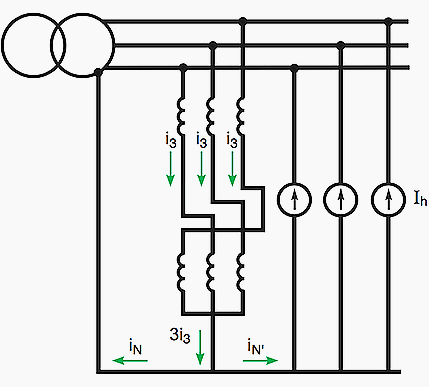
As a result, the impedance seen by the third order harmonic currents is very low (leakage inductance of the winding only). The zigzag reactance therefore produces a return path with low impedance to zero-sequence currents and harmonics of the third order and multiples of 3.
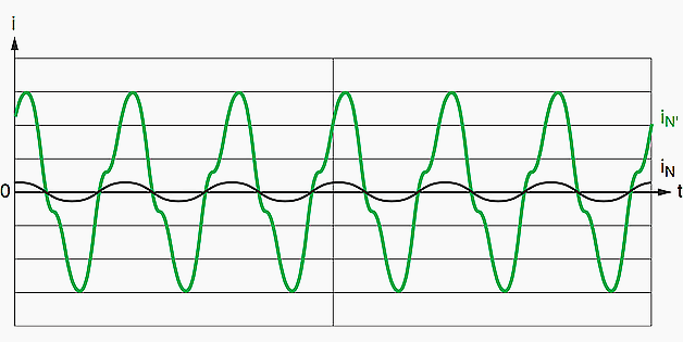
It therefore reduces the current circulating in the power supply neutral, as illustrated in Figure 2 , for single-phase loads.
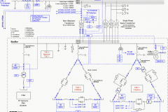
5. Third order filter in the neutral
The principle of this device consists of placing a trap circuit tuned to the third harmonic in series with the neutral conductor (see Figure 3 below).

Figure 4 illustrates the waveforms obtained, assuming that single-phase loads are connected between phase and neutral. The reduction in the neutral current is accompanied by an increase in voltage distortion, although this does not generally affect the operation of standard IT equipment.
![Waveforms: Line current [a] and neutral current [b] without filter; line current [c] and neutral current [d] with filter](https://electrical-engineering-portal.com/wp-content/uploads/2016/03/waveforms.png)
Reference // Cahier Technique Schneider Electric no. 212 – The neutral: A live and unique conductor by J. Schonek
Related electrical guides & articles


Edvard Csanyi
Hi, I'm an electrical engineer, programmer and founder of EEP - Electrical Engineering Portal. I worked twelve years at Schneider Electric in the position of technical support for low- and medium-voltage projects and the design of busbar trunking systems.I'm highly specialized in the design of LV/MV switchgear and low-voltage, high-power busbar trunking (<6300A) in substations, commercial buildings and industry facilities. I'm also a professional in AutoCAD programming.
Profile: Edvard Csanyi

My dear sirs,
Any rough thumb rule calculation for provision of number of earth elctrodes based on KVA rating on distribution transformer and on power transformers having a capacity of 1000 kva and 500 MVA respectiouly.
Excellent topic….. Thank you EEP
These are the technical solutions if 3rd order harmonics are present.
But the best approach is to reduce the THD: IEC recommendations and EMC limit the THD tp 3/5 % thus harmonics are not a real problem.
Only a few machines produce high level of harmonicas: large welding equipment, arc furnace, electrolitic cells. However, IEC gives rules for calculating the size of neutral, based on THD % (<15% N=1/2 Ph, – 30% to be calculated with a formula).
And don’t forget that modern electronic equipment like UPSs and VFDs produce a different kind of “noise”: high frequency components, that can overpass a transformer through capacitances.