Distortion of the fundamental sine wave
The presence of harmonic frequencies in addition to the fundamental 50Hz, bring about distortion of the fundamental sine wave. Considerable problems may arise dependant upon the level of this distortion.

Sources of harmonic distortion can be:
- Variable Speed Drives
- UPS equipment
- Non linear load (switch mode power supplies)
- Special industrial processes
- Resonant conditions with PFC capacitors
- Diesel generated supplies, cyclic engine/flywheel irregularities and full pitch winding alternators.
The Copper Development Association has produced two useful documents (publications 22 and 123), which include information relating to power quality and system reliability. The following formula, taken from publication 22 can be used to establish the depth of penetration in flat copper bar for various frequencies:
Depth of penetration,
![]()
Where:
- d – depth of penetration [mm]
- ρ – resistivity of copper [μς cm]
- f – frequency [Hz]
Example at fundimental, 50hz:
![]()
Examples at some harmonic frequencies:
| Harmonic | Frequency (Hz) | Depth of penetration (mm) |
| 3rd | f = 150Hz | d = 5.38 |
| 5th | f = 250Hz | d = 4.18 |
| 7th | f = 350Hz | d = 3.52 |
| 11th | f = 550Hz | d = 2.81 |
| 13th | f = 650Hz | d = 2.85 |
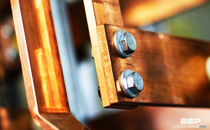
It can be seen that at 50Hz the penetration depth is just over 9mm therefore with conductors (or solid laminations) greater than 18mm thick, the centre of the conductor starts to be “void” of current. As the higher frequencies are considered e.g. the 13th (650 Hz) the centre of 6mm thick conductors is not being “reached”.
This definitely results in higher conductor temperatures than those expected under true sinusoidal conditions, encourages the use of conservatively rated copperwork and the adoption of air spaced conductor laminations rather than solid, butt-up, formations.
A further problem arises with harmonic currents in that unlike “normal” fundamental currents, the odd numbered i.e. 3rd, 5th, 7th etc. etc. harmonic currents do not vectorially add with a resultant as the neutral current – they arithmetically add and summate in the neutral.
This can result in neutral currents exceeding those of the phase currents.
Reference: Technical Considerations in the Specification of LV Switchboards – AF Swichgear


Edvard,
If you suspect harmonic distortion of the power system, how can one go about proving harmonic distortion with say measured values or detected states across he power system at different points.
I work in a hospital which I believe is a prime environment for harmonic distortion.
We use VSD across the site, we have capacitor PFC, our site is run off of CHP generators, we have numerous amounts of UPS systems and not to mention the various anounts of other equipment involving scanning and medical examinations/operations.
So I was wondering how one could detect and then implement measures to reduce the effect of harmonic distortion?
Hi Philip,
The best way to do this is do a survey of the infrastructure. Then complete a power survey there is an IEC std for EMC a percentage Allowable distortion on an LV system. Once you have completed this phase. You may find you may have to install an active harmonic filter to the various area on the system to correct the issue. Jope this helps
Best regards
Im Eletromecanic Engineer
Im Work in Angola as a service provider-
Gervásio Simão
How can we predict these kind of problems from the design, calculate them and take the dimmentional and needed precuations or solutions at the very beggining?