Filter circuits
The subject of this technical article are harmonic filters and their design. Filtering measures are recommended and may be required for electrical systems with too high harmonic levels. Filter circuits can absorb more harmonic currents.
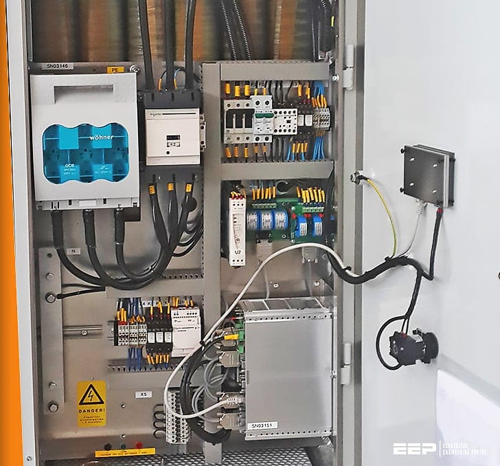
This means that, like reactor-protected systems, they consist of one series circuit of reactance and a capacitor.
Due to the many devices, for example with capacitive smoothing which generates harmonics (particularly the third, fifth and seventh harmonics), this causes undesirable network perturbations (or distortions).
- Passive Filters
- Active Filters
- Hybrid Filters
- Selection Criteria
- Harmonics Filters – IEEE 1531 Overview (VIDEO)
1. Passive Filters
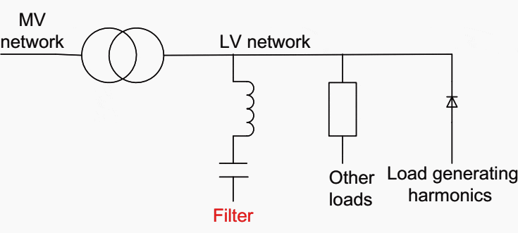
A passive filter consists of a series circuit of reactors and capacitors. Harmonic currents generated by, for example, a frequency converter are shunted by this circuit designed to have low impedance at a given frequency compared with the rest of the network.
The described function with a harmonics generator, impedance representing all other loads, a filter, and the medium voltage network are illustrated schematically in Figure 1.

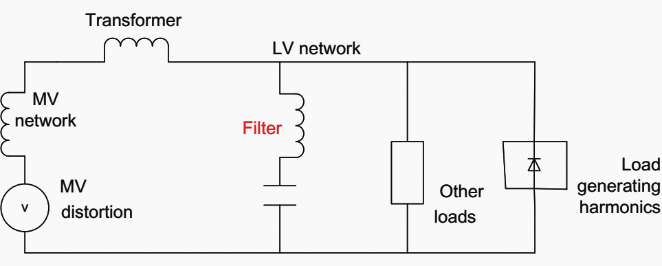
The equivalent circuit seen with the harmonics generator modeled as a harmonic current generator is shown in Figure 2. It includes the medium voltage (MV) network, and the voltage distortion is represented by a harmonic voltage generator.

As the passive filters offer very low impedance at the resonance frequency, the corresponding harmonic current will flow in the circuit whatever its magnitude.
Passive filters can get overloaded under which condition they will switch off or be damaged. The overload may be caused by the presence of unforeseen harmonics on the supply system or caused by structural modifications in the plant itself (such as the installation of a new drive).
The degree of filtering provided by the passive filter is given by its impedance in relation to all other impedances in the network. As a result, the filtration level of a passive filter cannot be controlled and its tuning frequency may change in time due to aging of the components or network modifications.
The quality of the filtration will then deteriorate.
It is also important to note that a passive filter circuit may only filter one harmonic component. A separate filter circuit is required for each harmonic that needs to be filtered.
In order to overcome the problems associated with traditional passive filters and in order to meet the continuing demand for good power quality, Active Filters have been developed for low voltage (LV) applications.
Figure 3 shows the simplified basic principle of a passive filter and its functions. The impedance progression of the filter shows the tuning to a certain harmonic frequency and the areas where resonance reinforcement may possibly occur.
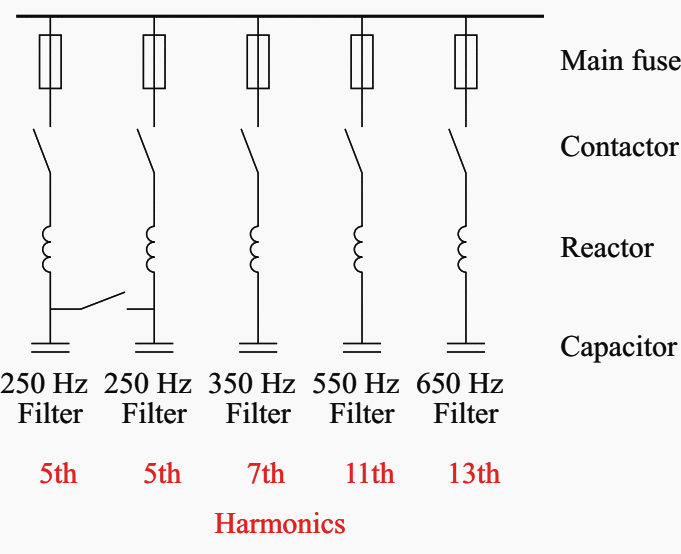

A passive filter can consist of several steps which are tuned to different frequencies. It can also consist of several steps for a certain frequency. The tuning frequency, capacity and network impedance determine the effectiveness of the filter.
One step is required for each harmonic up to the desired frequency.
With passive filters, the tuning frequencies of the filter steps are not precisely tuned to the harmonic currents to be filtered so that extremely high filter currents are avoided.
In addition, passive filtering is not only possible in the range from the 3rd to the 25th harmonic, but also possible even beyond this. Filter steps for all possible harmonics of a lower order must be present for each filter circuit, namely for higher harmonics, to prevent their reinforcement.
Passive filters are frequently implemented as tuned filters. In industrial networks, these filters are usually tuned to the harmonics of the order ν = 5, 7, 11, 13, . . . which are typical for inverters.
Passive filters – and reactor-protected compensation systems – are made of a series circuit of reactor and capacitor. The characteristic of series resonance is used here intentionally to divert harmonic currents for the specific frequency by using lower impedance.
This means that the network impedance/filter step current divider reduces the harmonic current flowing into the network and thus also the harmonic voltage in the network impedance.
In addition to the ‘fundamental frequency compensation power’ (basic harmonic reactive power) that is provided, the harmonic load ability thus becomes an important characteristic for passive filtering.
Due to tuning, filter circuits cannot be controlled like reactor power compensation. The generation of harmonics does not correlate with the compensation requirements. This means that the steps of the same tuning frequency can thus be overloaded if they are only switched on and off based on reactive power requirements.
This danger exists in particular when the demand for compensation is low and the generation of harmonics is high.
2. Active Filters
Active filters are systems employing power electronics. They are installed either in series or in parallel with the nonlinear load to provide the harmonic currents required by nonlinear load and thereby avoid distortion on the power system (Figure 4).
They are effective and recommended for the commercial installations comprising a set of devices generating harmonics with a total power rating less than 200 kVA (variable – speed drives, uninterruptible power supplies [UPSs], office equipment, etc.).
Also, they are used for the situations where the current distortion must be reduced to avoid overloads.
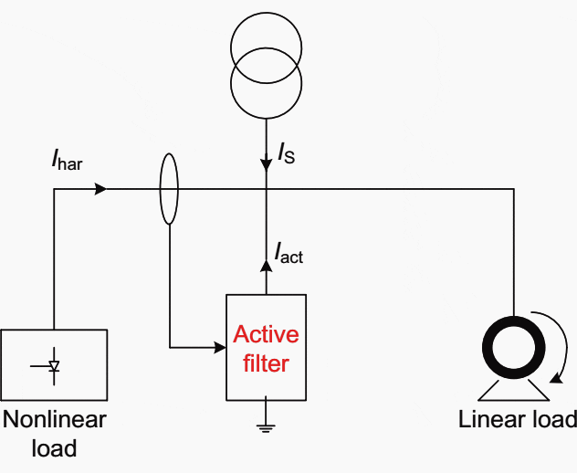

Where:
- Is = source current;
- Iact = current injected by active filter;
- Ihar = harmonic current generated by nonlinear load.
In general, active filters are special harmonic filters. The active filter is usually utilized in the form of a parallel filter. Note that this part does not analyse the differences between parallel filters and serial filters.
Sometimes, for the term ‘active filter’, the term ‘active harmonic filter’ is more common.
Active filters supply harmonic currents used by the consumer so that, under ideal conditions, only the fundamental frequency current is still obtained from the distribution network of the local distribution system operator (power utility).
Most active filters are digital (i.e. the harmonic spectrum is determined by amount and phase location from the current measurement and an appropriate counter-phase current spectrum is generated).
Most of the ‘active harmonic filters’ on the market today are current controlled and can filter the harmonic current of a measured load. The harmonic level from the MV or the harmonic generators outside the measuring circuit are not affected by this.
Active filters can filter harmonic currents up to their nominal current, whereby an individual so-called derating factor (reduction factor) must be considered for every specific frequency.
Examples of typical applications of the active filter are:
- Distribution networks in office buildings with a lot of nonlinear loads which cause a total harmonic distortion of THD-I · S/Sr > 20%.
- Distribution networks whose voltage distortion caused by harmonic currents must be reduced to avoid malfunctions of sensitive loads.
- Distribution networks whose harmonic current must be reduced to avoid overloads; in particular, those of the neutral conductor.
Some additional typical applications are as follows:
- Power inverter load with high harmonic feedback and low reactive power requirements.
- Networks with a high share of the third harmonic due to the use of single-phase consumers.
Some important characteristics of active filters are as follows:
- Most active filters are current controlled.
- They can be used without any problems as distributed filters for selected system parts.
- High power density and thus low space requirements.
- Reactive power compensation is possible, but this requires expensive resources of the filter.
- Selective filtering of individual frequencies.
- Active solutions are much more flexible in their use but also more expensive.
- Active filters cannot be overloaded regarding harmonic filtering.
Some advantages of active filters are:
- Reactive power compensation
- Dynamic compensation
- Load balancing
- Flicker compensation
- Tuned filter circuits
- Energy savings
- Voltage stabilization
3. Hybrid Filters
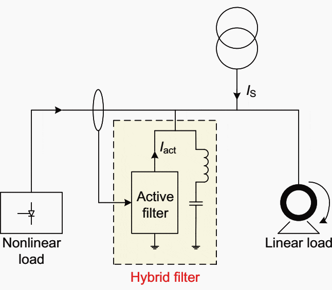
The two types of filters presented above can be combined in a single device, thus constituting a hybrid filter.
This type of filtering solution combines the advantages of the existing systems and provides a high performance solution covering a wide power range (Figure 5).

The hybrid filters are adequate to be used for the following typical applications:
- Industrial installations comprising a set of devices causing harmonics with a total power rating in the range of 200 kVA or more (variable speed drives, UPSs, rectifiers, etc.);
- Situations where voltage distortion must be reduced to avoid disturbing sensitive loads;
- Situations where conformity with strict harmonic emission limits is required;
- Installations where PF correction is required; and
- Situations where current distortion must be reduced to avoid overloads.
Selection criteria
From the above explanation of filters and types of filters, it is possible to choose a suitable type of filter with the following criteria.
Passive filters offer both PF correction and large capacity for current filtering. Installations where the passive filters are installed must be sufficiently stable, that is, a low level of load fluctuations. If a high level of reactive power is supplied, it is advised to de-energize the passive filter when load levels are low.
Active filters compensate for harmonics over a wide range of frequencies. They can adapt to any load. However, their conditioning capacity is limited.
Hybrid filters combine the strong points of both passive filter and active filters.
Harmonics Filters – IEEE 1531 Overview
In this webinar, taught by Pablo De Jarmy, at Projar in Mexico, he discusses best practices in harmonic filter design by giving an overview of the IEEE 1531 standard. After a harmonic filter is specified for a given frequency and kVAr capacity, many other factors have to be considered for the final specification, as the filter will almost certainly not operate under ideal conditions.
IEEE 1531 standard provides a guide to design the filter to overcome these less tan ideal conditions and help assure the filter will work without further issues.
Sources:
- Electric distribution systems by Abdelhay A. Sallam and Om P. Malik
- Reactive power compensation – A practical guide by Wolfgang Hofmann (Reactive Power Engineering, Munich, Germany), Jurgen Schlabbach (University of Applied Sciences, Bielefeld, Germany) and Wolfgang Just (Engineering Consultant, Dorsten, Germany)


Dear Sir,
Very informative article
I will definitely get back to you for queries.
Regards,am an electrician.would like to be informed on harmonics fault and diagnosis,
Great article! Thanks for sharing this with us.
Dear sir
I have some question about passive single tuned filter
1_can we use from Delta connection capacitor instead star in this kind of filter
2_How can we calculate the network impedance?
Regards
Very informative article.
In calculating the active filter, most manufacturers recommend for capacitor batteries to select the de-tuning reactor. Is there a methodology for choosing the reactor, provided that the active filter is before the capacitor batteries?