
Estimated Study Time: 19 minutes
The harmonic distortion in network
The harmonic currents are mainly down to the nonlinear loads in the installations. The most frequent harmonic sources are linked to the use of electric arcs (welding, arc furnaces, discharge lamps, etc.) and to magnetic machines.
 The study of harmonics and LV energy compensation
Power electronics (converters, variable control units, power supplies, ballasts, induction heating) is also a significant source of harmonics in the industrial field.
An additional source has recently appeared with the increased use of the following products amongst the general public and in the commercial area, which are all low-power devices but are in widespread use: computers, printers, televisions and small applicators that all have common electrical switching mode power supplies.
The new forms of “low consumption” economic lighting are also new sources of harmonics.
One new feature: distorting power that is due to harmonics must be calculated in any electrical assessment going forward.
For these latter devices, apart from creating additional losses through hysteresis due to the increase in frequency, the presence of harmonics with higher frequency than that of the network leads to a decrease in the impedance of the capacitors, which results in overload currents and even destruction in the event of resonance.
Depending on the “total harmonics” present, suitable compensation solutions will have to be implemented, or solutions that include suitable protective devices from the risk of resonance with harmonics.
The design of the installation considered and calculation of the elements present which may be completed using on-site measurements will be essential in getting rid of resonance risk, the causes and consequences.
- The characterisation of harmonic interference
- The behaviour of the capacitors with the presence of harmonics
- Harmonic current circulation
- Filtering and elimination of harmonics
- Types of filter in short
1. The characterisation of harmonic interference
This distortion corresponds to unnecessary power consumption at multiple frequencies of the fundamental frequency. The distorted current matches the superposition of the various harmonic orders.


Harmonic interference can be characterized using several methods:
- By its value (in amps or volts) for each harmonic order (multiple of the fundamental frequency)
- By the total harmonic distortion (THD) in % which quantifies the harmonic signal part (defined in voltages or in currents) in relation to the sinusoidal fundamental wave.
- By the corresponding harmonic power or distorting power D.
1.1. Calculation of the value of each harmonic order with reference to its frequency
Where:
- Y0: value of the Dc component generally nil
- Yh: effective value of the n-order harmonic,
- ω: angular frequency of the fundamental frequency,
- ϕh: phase shift of the harmonic component to t = 0.
1.2. Calculation of harmonic distortion (HD) and of total harmonic distortion (THD)
This magnitude is used to assess voltage or current distortion using a unique number. In practice, the total harmonic distortion is usually expressed as a percentage by limiting the range (most often order 25, or 40 or 50 in the event of high pollution).
1.3. Calculation of harmonic pollution or distorting power
With harmonics present, the actual apparent power represents the geometric sum of the voltage/current products of each harmonic order.
The effective value l of the current is determined by the contribution of the currents of each harmonic order. The apparent power due to orders higher than 1 (fundamental order) constitutes the harmonic power or distorting power D.
The active power P and reactive power Q are linked to the current of the 1st fundamental order. The distorting power is linked to the harmonic orders higher than 1.
The distorting power D increases the apparent power s and damages the power factor λ.
In the event of very high harmonic power, the critical frequencies must be eliminated or minimized using suitable filters. there are several technological possibilities: passive, active, hybrid.
3 points important to note:
Point #1
The THD does not provide any information on the spectral contents of the signal, and therefore does not constitute adequate means for calculating filtering methods in relation to resonance risks.
On the other hand, it does give an interesting indication of the installation’s degree of pollution and of the risks incurred.
Point #2
The voltage THDu characterises the voltage wave distortion.
- A THDu value of less than 5% is considered normal: there is no fear of malfunction.
- A THDu value between 5% and 8% still complies with the standard EN 50160 but does reveal significant harmonic pollution and some malfunctions are possible.
- A THDu value higher than 8% reveals high harmonic pollution: malfunctions are probable. an in-depth analysis and the implementation of filtering devices are required.
Point #3
The voltage THDi characterises the current wave distortion.
- A THDi value lower than 10% or even 15% is considered normal: there is no fear of malfunction.
- A THDi value of between 15% and 35% (standard value 33%) reveals significant harmonic pollution: there is a risk of overheating, which involves oversizing of the cables and the power supplies.
- A THDi value higher than 35% reveals high harmonic pollution: malfunctions are probable.
It is, therefore, important to know the exact nature (the order) of the harmonics and, in particular, the potential part of order 3 which is often predominant. Use of harmonics compensation devices is recommended. This becomes essential beyond 50% THDi.
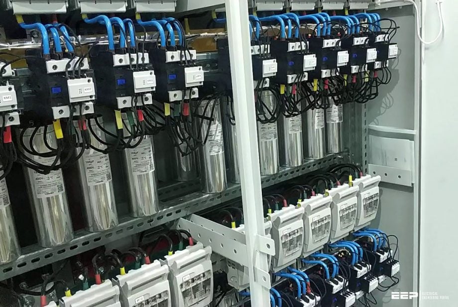
2. The behaviour of the capacitors with the presence of harmonics
The harmonics circulate preferentially in the capacitors at the risk or overloading and destroying them. The impedance of a capacitor is inversely proportional to the frequency (Zc = 1/cω).
The more the frequency increases (the case with harmonics), the more the impedance decreases.
Introducing capacitors, however, also has the effect of changing the impedance of the installation compared with that of the source, therefore risking resonance phenomenon occurring between the two, which is all the more easily attained given the fact of the frequency increase, i.e. the case where harmonic currents are present.
The amplification factor is used to calculate the resonance risk according to the power compensation QC compared with the source power ST (or of its short-circuit power SSC), with this factor also dependent on the active power load P.
These two factors are used to balance the choice in a practical way through assessing the risk of harmonic pollution of the installation SH/ST compared with the power compensation used QC/ST.
Important to note!
The installation’s total harmonic distortion level and the compensation rate are two essential factors in choosing capacitor type. The more distorting loads incorporated in the installation and/or the more significant the compensation compared with the power supply, the higher the risk of harmonic overload of the capacitors.
Solutions that incorporate protective devices are therefore required.
Care should be taken when installing compensation capacitors in low-power installations with several distorting loads (shops, offices, etc.)
3. Harmonic current circulation
3.1. installation without capacitors
The harmonic currents circulate naturally or “go back up” from their source to the circuits which show the lowest impedance. In theory, most of these (Ihs) are therefore sent back towards the source and the network by crossing the power supply transformer.

In practice, harmonic currents (Ihu) are also fed back into the other load circuits of the installation: mutual pollution between harmonic generators and sensitive reactors is therefore possible.
An installation’s sensitivity to the harmonics that it generates is of course linked to the quantity of these harmonics, and especially to the impedance characteristics of the installation in relation to the source.
Equivalent wiring diagram
- Impedance of the source ZS = √(RS2 + XS2)
- Impedance of the harmonic generator receiver and of its power supply line Zu = √(RL2 + XL2)
If ZS << ZU, the voltage Va = e, the source and the upstream system acts as one ideal voltage source. The network is “immensely powerful” compared with the installation to be supplied.
Frequency behaviour is linear, i.e. the contribution of the different harmonic orders does not change the voltages VA and VB in the mathematical application of the superposition theorem known as “de Parseval”:
This same concept is used to link the harmonic pollution probability with the power of the source and the polluting element ratio. The inequality is transposed to the power in the form:
SSC >> SU
Where:
- SSC: short-circuit power of the impedance source ZS
- SU: apparent power of the impedance pollution receiver ZU
The same approach has been shown to the resonance risk between source and installation.
3.2. Installation with capacitors
The installation of capacitors changes the harmonics circulation. The capacitors’ impedance is lower than that of the source when the frequency increases.
The behaviour of the entire source/installation is changed and varies according to the harmonics frequency.

From a mathematical point of view, the superposition theorem no longer applies and calculation of the contribution of each harmonic order would show that impedance ZU decreases with the frequency.
On the equivalent wiring diagram, the voltage VA differs from e.
A significant Ihc part of the harmonic currents is diverted towards the capacitor. There is a risk therefore of the latter being overloaded or destroyed.
4. Filtering and elimination of harmonics
With significant harmonics present (SH/ST: 25 to 35%), installation of an inductance in series with the capacitor (type with anti-resonance reactor) can be used to increase the impedance of the latter to harmonic frequencies and to move the resonance frequency of the LC filter thus created below the frequencies due to the main harmonic currents.
This technique has its limits. It partially eliminates the harmonic currents, but a part continues to revert to the source.
Typical tuning frequency values:
- Close to 200 Hz (networks up to 50 Hz) and to 240 Hz (networks up to 60 Hz): eliminates the possible resonance with the order-5 harmonic (for three-phase systems where the order-3 harmonic is reduced or eliminated)
- Close to 135 Hz (networks up to 50 Hz) and to 160 Hz (networks up to 60 Hz) for three-phase systems where the order-3 harmonic is predominant.
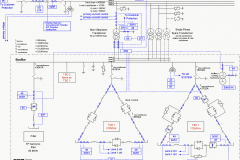
Example of the layout of an anti-resonance reactor in series with the capacitor. The order-5 harmonic showing a resonance risk is stopped and is not tuned to the capacitor.
It is not eliminated, however, and continues to circulate in the installation, risking other receivers becoming polluted.
The two components are sized in such a way that they resonate at the unwanted frequency, thus leading the current to run through the filter. As such different “tuned” filters can each be installed on the frequency to be eliminated (250 Hz for order 5, 350 Hz for order 7).
The advantage of these solutions is the simplicity and the limited cost.
The filter absorbs the harmonic and prevents resonance starting with the compensation capacitor.
Depending on the position of the filter in the installation it allows the circulation of the “captured” harmonic to be decreased. the filter must be sized so as to absorb currents that may be high where
resonance occurs.
5. Types of filter in short
Passive filter
The passive filter is made up of an inductance in series with a capacitor. The LC cell made up in this
way is connected to a given (order) harmonic frequency.
Its installation in parallel does not limit the power field. It is a solution that is completely compatible with the power compensation from the moment that an analysis of the harmonic content of the installation has been carried out.
The active filter
The active filter analyses the harmonics that circulate around the installation in real time (current harmonics) or that are present at the terminal of a sensitive receiver (voltage harmonics).
It adapts according to the load but has a higher cost and its power remains limited.

The hybrid filter
This is an association of two systems, passive and active, which is used to extend the power area.
Harmonics filtration is effective as long as a suitable system is chosen, which means that analysis and prior measurements are essential. if these are not completed then malfunctions are inevitable.
Reference // Electrical energy supply by Legrand
Related electrical guides & articles


Edvard Csanyi
Hi, I'm an electrical engineer, programmer and founder of EEP - Electrical Engineering Portal. I worked twelve years at Schneider Electric in the position of technical support for low- and medium-voltage projects and the design of busbar trunking systems.I'm highly specialized in the design of LV/MV switchgear and low-voltage, high-power busbar trunking (<6300A) in substations, commercial buildings and industry facilities. I'm also a professional in AutoCAD programming.
Profile: Edvard Csanyi

Muscat, Oman… What if only the cables near contactor terminals are overheated or burned? What could be the issue? We have lots of it in our Abb panels. Please advice.
Dear Ed
Your featured publications are interesting. Can you please write me with information on remedial filters for different distortions
thinks