
Estimated Study Time: 5 minutes
Harmonics related problem
If a plant engineer suspects that he might have a harmonics related problem, the following steps can easily be performed as an initial investigation into potential problems:
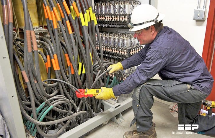 4 steps to diagnose a potential harmonics related problem (photo credit: en-us.fluke.com)
Step #1
Look for symptoms of harmonics as listed in Table 1 below. If one or more of these symptoms occurs with regularity, then the following steps should be taken.
| Equipment | Consequences |
| Current Harmonic Distortion Problems | |
| Capacitors | Blown fuses, reduced capacitor life |
| Motors | Reduced motor life, inability to fully load motor |
| Fuses/breakers | False/spurious operation, damaged components |
| Transformers | Increased copper losses, reduced capacity |
| Voltage Harmonic Distortion Problems | |
| Transformers | Increased noise, possible insulation failure |
| Motors | Mechanical fatigue |
| Electronic loads | Misoperation |
Step #2
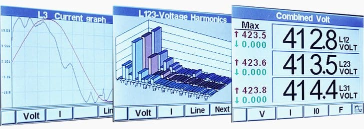
If the plant contains power factor correction capacitors, the current into the capacitors should be measured using a “true rms” current meter. If this value is higher than the capacitor’s rated current at the system voltage (by >5% or so), the presence of harmonic voltage distortion is likely.
Step #3
Conduct a paper audit of the plant’s harmonic-producing loads and system configuration. This analysis starts with the gathering of kVA or horsepower data on all the major nonlinear devices in the plant, all capacitors, and rating information on service entrance transformer(s).
Step #4
If the electrical distribution system is complex – for example, multiple service entrances, distributed capacitors – or if the paper audit is incomplete or considered to be too burdensome, the most definitive way to determine whether harmonics are causing a problem is through an on-site plant audit.
This audit involves an inspection of the electrical system layout and connected loads, as well as harmonic measurements taken at strategic locations.
This data can then be assembled and analyzed to obtain a clear and concise understanding of the power system. Many companies provides an engineering service to conduct these on-site plant audits.
Performing a system analysis to correctly apply harmonic filters
The proper application of harmonic filters can be greatly simplified by recognizing that there are only a few pieces of pertinent information and analysis steps that need to be taken for most systems in order to correctly deal with the problem.
Rather, it should rely on the relatively few pieces of information that are required to make the correct applications decision. If this information indicates that some type of metering and measurement is required, then only those select measurements that yield useful information will be performed, keeping the complexity and cost to a minimum without sacrificing solution correctness.
One of the most basic and useful pieces of information that must be known before attempting to correct power factor in the presence of nonlinear loads is the ratio of the total nonlinear kVA to the service transformer kVA rating.
This ratio alone can often be used to determine whether harmonic filters are necessary to correct power factor or whether plain capacitors can be added without experiencing problems as follows:
- If the plant’s total three-phase nonlinear load (in kVA, 1 hp = 1 kVA) is more than 25% of the main transformer capacity, harmonic filters will almost always be required for power factor correction
- If the plant’s total three-phase nonlinear load is less than 15% of the main transformer capacity, capacitors can usually be applied without problems
- If the plant’s total nonlinear load is between 15 and 25%, other factors should be considered
Reference // Power factor correction – A guide for the plant engineer by Eaton
Related electrical guides & articles


Edvard Csanyi
Hi, I'm an electrical engineer, programmer and founder of EEP - Electrical Engineering Portal. I worked twelve years at Schneider Electric in the position of technical support for low- and medium-voltage projects and the design of busbar trunking systems.I'm highly specialized in the design of LV/MV switchgear and low-voltage, high-power busbar trunking (<6300A) in substations, commercial buildings and industry facilities. I'm also a professional in AutoCAD programming.
Profile: Edvard Csanyi
