
Estimated Study Time: 26 minutes
Busbar protection
Most of HV busbar faults involve single-phase and earth, but faults may arise from many different causes. The number of faults that stand out is between phases clear of earth. In fact, a large proportion of busbar faults result from human error rather than the failure of switchgear components.
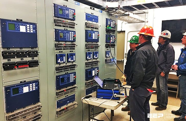 Relay settings and applying high-impedance differential busbar protection scheme (photo credit: premierpower.us)
Since there are several different protections of busbar (and their combinations) that are in use nowadays, this technical article will focus only on high impedance differential protection and its implementation.
High impedance differential protection
Busbar protection in form of high impedance differential protection is still in common use nowadays. The considerations that have to be taken into account are detailed in the following sections.
- Stability
- Effective setting or primary operating current
- Check feature
- Supervision of CT secondary circuits
- Arrangement of CT connections
- Summary of practical details
1. Stability
The incidence of fault current with an initial unilateral transient component causes an abnormal build-up of flux in a current transformer.
When through-fault current traverses a zone protected by a differential system, the transient flux produced in the current transformers is not detrimental as long as it remains within the substantially linear range of the magnetizing characteristic.
With fault current of appreciable magnitude and long transient time constant, the flux density will pass into the saturated region of the characteristic. This will not in itself produce a spill output from a pair of balancing current transformers provided that these are identical and equally burdened.
The faulted circuit is many times more heavily loaded than the others and the corresponding current transformers are likely to be heavily saturated, while those of the other circuits are not. Severe unbalance is therefore probable, which, with a relay of normal burden, could exceed any acceptable current setting.
For this reason such systems were at one time always provided with a time delay, but….
This practice is, however, no longer acceptable. It is not feasible to calculate the spill current that may occur, but, fortunately, this is not necessary.
An alternative approach provides both the necessary information and the technique required to obtain a high performance. An equivalent circuit, as in Figure 1, can represent a circulating current system.

The current transformers are replaced in the diagram by ideal current transformers feeding an equivalent circuit that represents the magnetizing losses and secondary winding resistance, and also the resistance of the connecting leads.
These circuits can then be interconnected as shown, with a relay connected to the junction points to form the complete equivalent circuit.
It should be noted that this is not the equivalent of a physical short circuit, since it is behind the winding resistance RCTH.
Applying the Thévenin method of solution, the voltage developed across the relay will be given by:

The current through the relay is given by:
If RR is small, IR will approximate to If, which is unacceptable. On the other hand, if RR is large IR is reduced. Above equation can be written, with little error, as follows:
or alternatively (Equation 1):
![]()
It is clear that, by increasing RR, the spill current IR can be reduced below any specified relay setting. RR is frequently increased by the addition of a series-connected resistor which is known as the stabilising resistor.
It can also be seen from the Equation 1 that it is only the voltage drop in the relay circuit at setting current that is important. The relay can be designed as a voltage measuring device consuming negligible current; and provided its setting voltage exceeds the value Vf of Equation 1, the system will be stable.
In fact, the setting voltage need not exceed Vf, since the derivation of Equation 1 involves an extreme condition of unbalance between the G and H current transformers that is not completely realised. So a safety margin is built-in if the voltage setting is made equal to Vf.
If the relay requires more time to operate than the effective duration of the DC transient component, or has been designed with special features to block the DC component, then this factor can be ignored and only the symmetrical value of the fault current need be entered in Equation 1. If the relay setting voltage, VS , is made equal to Vf, that is, If (RL + RCT), an inherent safety factor of the order of two will exist.
In the case of a faster relay, capable of operating in one cycle and with no special features to block the DC component, it is the r.m.s. value of the first offset wave that is significant. This value, for a fully offset waveform with no d.c. decrement, is √3If.
If settings are then chosen in terms of the symmetrical component of the fault current, the √3 factor which has been ignored will take up most of the basic safety factor, leaving only a very small margin.
Finally, if a truly instantaneous relay were used, the relevant value of If would be the maximum offset peak. In this case, the factor has become less than unity, possibly as low as 0.7.
It is therefore possible to rewrite Equation 1 as:
where:
- ISL = stability limit of scheme
- VS = relay circuit voltage setting
- RL + RCT = lead + CT winding resistance
- K = factor depending on relay design (range 0.7 – 2.0)
It remains to be shown that the setting chosen is suitable in next section ‘Effective Setting or Primary Operating Current‘.
The current transformers will have an excitation curve which has not so far been related to the relay setting voltage, the latter being equal to the maximum nominal voltage drop across the lead loop and the CT secondary winding resistance, with the maximum secondary fault current flowing through them.
Under in-zone fault conditions it is necessary for the current transformers to produce sufficient output to operate the relay.
In order to cater for errors, it is usual to specify that the current transformers should have a knee-point e.m.f. of at least twice the necessary setting voltage. A higher multiple is of advantage in ensuring a high speed of operation.
2. Effective Setting or Primary Operating Current
The minimum primary operating current is a further criterion of the design of a differential system. The secondary effective setting is the sum of the relay minimum operating current and the excitation losses in all parallel connected current transformers, whether carrying primary current or not.
This summation should strictly speaking be vectorial, but is usually done arithmetically.
It can be expressed as (Equation 2):
![]()
where:
- IR = effective setting
- IS = relay circuit setting current
- IeS = CT excitation current at relay voltage setting
- n = number of parallel connected CTs
Having established the relay setting voltage from stability considerations, as shown in previous section, and knowing the excitation characteristic of the current transformers, the effective setting can be computed.
The secondary setting is converted to the primary operating current by multiplying by the turns ratio of the current transformers. The operating current so determined should be considered in terms of the conditions of the application.
For a phase and earth fault scheme the setting can be based on the fault current to be expected for minimum plant and maximum system outage conditions.
- Phase-phase faults give only 86% of the three-phase fault current
- Fault arc resistance and earth path resistance reduce fault currents somewhat
- A reasonable margin should be allowed to ensure that relays operate quickly and decisively
It is desirable that the primary effective setting should not exceed 30% of the prospective minimum fault current.
In the case of a scheme exclusively for earth fault protection, the minimum earth fault current should be considered, taking into account any earthing impedance that might be present as well. Furthermore, in the event of a double phase to earth fault, regardless of the inter-phase currents, only 50% of the
system e.m.f. is available in the earth path, causing a further reduction in the earth fault current.
The primary operating current must therefore be not greater than 30% of the minimum single-phase earth fault current.
In order to achieve high-speed operation, it is desirable that settings should be still lower, particularly in the case of the solidly earthed power system. The transient component of the fault current in conjunction with unfavourable residual flux in the CT can cause a high degree of saturation and loss of output, possibly leading to a delay of several cycles additional to the natural operating time of the element.
This will not happen to any large degree if the fault current is a larger multiple of setting.
For example, if the fault current is five times the scheme primary operating current and the CT knee-point e.m.f. is three times the relay setting voltage, the additional delay is unlikely to exceed one cycle.
The primary operating current is sometimes designed to exceed the maximum expected circuit load in order to reduce the possibility of false operation under load current as a result of a broken CT lead.
An overall earth fault scheme for a large distribution board may be difficult to design because of the large number of current transformers paralleled together, which may lead to an excessive setting.
It may be advantageous in such a case to provide a three-element phase and earth fault scheme, mainly to reduce the number of current transformers paralleled into one group.
Extra-high-voltage (EHV) substations usually present no such problem. Using the voltage-calibrated relay, the current consumption can be very small. A simplification can be achieved by providing one relay per circuit, all connected to the CT paralleling buswires.
This enables the trip circuits to be confined to the least area and reduces the risk of accidental operation.
3. Check Feature
Schemes for earth faults only can be checked by a frame-earth system, applied to the switchboard as a whole, no subdivision being necessary.
For phase fault schemes, the check will usually be a similar type of scheme applied to the switchboard as a single overall zone. A set of current transformers separate from those used in the discriminating zones should be provided.
No CT switching is required and no current transformers are needed for the check zone in bus-coupler and bus-section breakers.
4. Supervision of CT Secondary Circuits
Any interruption of a CT secondary circuit up to the paralleling interconnections will cause an unbalance in the system, equivalent to the load being carried by the relevant primary circuit.
Even though this degree of spurious output is below the effective setting the condition cannot be ignored, since it is likely to lead to instability under any through fault condition.
See Figure 2 and Figure 3.

The alarm relay is set so that operation does not occur with the protection system healthy under normal load.
Subject to this provison, the alarm relay is made as sensitive as possible. The desired effective setting is 125 primary amperes or 10% of the lowest circuit rating, whichever is the greater.
Since a relay of this order of sensitivity is likely to operate during through faults, a time delay, typically of three seconds, is applied to avoid unnecessary alarm signals.
5. Arrangement of CT Connections
It is shown in Equation 1 above how the setting voltage for a given stability level is directly related to the resistance of the CT secondary leads. This should therefore be kept to a practical minimum.
In a double bus installation, the CT leads should be taken directly to the isolator selection switches. The usual arrangement of cables on a double bus site is as follows:
- Current transformers to marshalling kiosk
- Marshalling kiosk to bus selection isolator auxiliary switches
- Interconnections between marshalling kiosks to form a closed ring

The relay for each zone is connected to one point of the ring bus wire. For convenience of cabling, the main zone relays will be connected through a multicore cable between the relay panel and the bus section-switch marshalling cubicle.
The reserve bar zone and the check zone relays will be connected together by a cable running to the bus coupler circuit breaker marshalling cubicle.
It is possible that special circumstances involving onerous conditions may over-ride this convenience and make connection to some other part of the ring desirable.
When the reserve bar is split by bus section isolators and the two portions are protected as separate zones, it is necessary to common the bus wires by means of auxiliary contacts, thereby making these two zones into one when the section isolators are closed.
6. Summary of Practical Details
This section provides a summary of practical considerations when implementing a high-impedance busbar protection scheme.
6.1 Designed stability level
For normal circumstances, the stability level should be designed to correspond to the switchgear rating.
Even if the available short-circuit power in the system is much less than this figure, it can be expected that the system will be developed up to the limit of rating.
6.2 Current transformers
Current transformers must have identical turns ratios, but a turns error of one in 400 is recognized as a reasonable manufacturing tolerance. Also, they should preferably be of similar design and where this is not possible the magnetizing characteristics should be reasonably matched.
6.3 Setting voltage
The setting voltage is given by the equation:
where:
- If = Steady state through fault current
- VS = relay circuit voltage setting
- RL = CT lead loop resistance
- RCT = CT secondary winding resistance
6.4 Knee-point voltage of current transformers
This is given by the formula:
![]()
6.5 Effective setting (secondary)
The effective setting of the relay is given by:
![]()
where:
- IS = relay circuit setting current
- IeS = CT excitation current at relay voltage setting
- n = number of parallel connected CTs
For the primary fault setting multiply IR by the CT turns ratio.
6.6 Current transformer secondary rating
It is clear from Equation 1 and Equation 2 above that it is advantageous to keep the secondary fault current low. This is done by making the CT turns ratio high. It is common practice to use current transformers with a secondary rating of 1A.
Although a lower ratio, for instance 400/1, is often employed, the use of the optimum ratio can result in a considerable reduction in the physical size of the current transformers.
6.7 Peak voltage developed by current transformers
Under in-zone fault conditions, a high impedance relay constitutes an excessive burden to the current transformers, leading to the development of a high voltage.
When the burden resistance is finite although high, an approximate formula for the peak voltage is:
where:
- Vp = peak Voltage developed
- VK = saturation Voltage
- VF = prospective Voltage in absence of saturation
This formula does not hold for the open circuit condition and is inaccurate for very high burden resistances that approximate to an open circuit, because simplifying assumptions used in the derivation of the formula are not valid for the extreme condition.
Another approach applicable to the open circuit secondary condition is:
where:
- If = fault current
- Iek = exciting current at knee-point voltage
- Vk = knee-point voltage
Any burden connected across the secondary will reduce the voltage, but the value cannot be deduced from a simple combination of burden and exciting impedances.
These formulae are therefore to be regarded only as a guide to the possible peak voltage. With large current transformers, particularly those with a low secondary current rating, the voltage may be very high, above a suitable insulation voltage.
The voltage can be limited without detriment to the scheme by connecting a ceramic non-linear resistor in parallel with the relay having a characteristic given by:
![]()
where:
- C is a constant depending on dimensions and
- β is a constant in the range 0.2 – 0.25.
The current passed by the non-linear resistor at the relay voltage setting depends on the value of C.
6.8 High impedance relay
Instantaneous attracted armature relays or numeric relays that mimic the high impedance function are used. Simple fast-operating relays would have a low safety factor constant in the stability equation, as discussed in first section ”Stability”.
An alternative technique used in some relays is to apply the limited spill voltage principle shown in Equation 1. A tuned element is connected via a plug bridge to a chain of resistors and the relay is calibrated in terms of voltage.
Reference // Network protection and automation guide by Alstom Grid
Related electrical guides & articles


Edvard Csanyi
Hi, I'm an electrical engineer, programmer and founder of EEP - Electrical Engineering Portal. I worked twelve years at Schneider Electric in the position of technical support for low- and medium-voltage projects and the design of busbar trunking systems.I'm highly specialized in the design of LV/MV switchgear and low-voltage, high-power busbar trunking (<6300A) in substations, commercial buildings and industry facilities. I'm also a professional in AutoCAD programming.
Profile: Edvard Csanyi

CT secondary in high impedance busbar protection is paralleled and taken to the relay through a stabilizing resistor. Neutral side of the paralleled CTs is also grounded through a link. Why is this grounding provided in only one place and not in multiple places?
Multiple ratio CT is suitable for High Impedance protection (Busbar or REF…)
it is important when you mention hight impedance to think about thevin’s and northon theoreme
for more detail as a remembering follow https://www.youtube.com/watch?v=WBCT4k7rJDk website
thank you
differential protectionis is known for its well selectivity. but when it deals with a huge electrical network which is not causal, the succession of responses, is under subject to isolate optimally a certaine zone by setting the operating point, or to set the delay , or the time response it is necessary or helpfull to have a flowchart to follow or to situate the idea think about boolean algebra and for optimization there exist too many ways of analysis among them which is the simplest is the karnauph map when it is necessary to set the delay the time response the sensitivity such that to overcome te overlap and to isolate the rest of the network whether it is causal or not causal.
i agree with you but it is also helpfull to follow this procedure whenever the network is cumbersome to use the flowchart, the graphs and if possible to think about boolean algebra for optimisation the priority about which respond taking note about the time response of each apparatus under subject. the logic is if necessary think like kanauph map to situate the succestion of which element in the network has to respond before the rest. to overcome the overlap or the shutdown , etc.
As i understand it is very necessary to think about bridges and as you know there are many sorts of bridges. according to me it is the idea.