
Estimated Study Time: 11 minutes
High potential “Hi-Pot” DC testing
This technical article provides general guidelines for high potential “Hi-Pot” DC testing of MV power cables. All tests made following cable installation and during the warranty period must be performed in accordance with the applicable specifications.
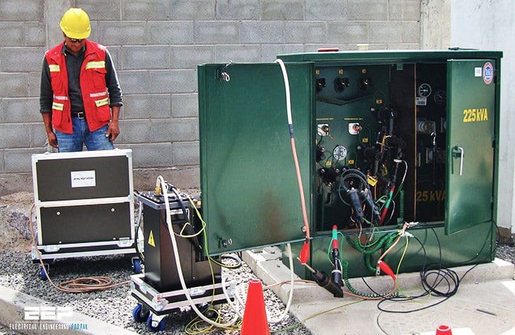 High potential (Hi-Pot) DC testing guidelines for medium voltage cables (photo credit: seiq.com.mx)
Testing should be performed by qualified personnel taking all appropriate safety precautions. The responsible safety officer should be consulted regarding the equipment and the appropriate personnel protection requirements.
In fact, these tests can result in damage to the cable insulation.
Humidity, condensation and actual precipitation on the surface of a cable termination can increase the leakage current by several orders of magnitude.
Humidity also increases the corona current, which is included in the total leakage current. Wind prevents the accumulation of space charges at all bare energized terminals. This results in an increase of corona. It is desirable to reduce or eliminate corona current at the bare metal extremities of cable or terminations. This may be accomplished by covering these areas with plastic envelopes, plastic or glass containers, plastic wrap, or suitable electrical putty.
Let’s see now the general guidelines for high potential (Hi-Pot) DC testing of medium voltage cables:
1. Pre-test guidelines
a. Testing equipment
Direct current test equipment is commercially available with a wide range of voltages. The Operator’s Manual for the particular test set being used should be read and well understood.
b. Recommended testing procedures
Acceptable procedures for conducting Hi-Pot testing, although varying slightly in technique, have been standardized as either a “withstand test” or a “time-leaking current test”. IEEE Std 400 provides additional information on DC testing and evaluation of the insulation of shielded power cable systems.
c. Preparation for testing
Before conducting any Hi-Pot testing, the following steps should be taken.
- All equipment, such as transformers, switches, taps, motors, circuit breakers, surge arrestors, etc., must be disconnected from the cable circuit to prevent damage to equipment and will prevent test interruptions due to flashovers or trip-outs resulting from excessive leakage current.
- Provide adequate clearance (about 2.5 ft) between the circuit test ends and any grounded object, and to other equipment not under test.
- Ground all circuit conductors not under test including the cable shields and nearby equipment.
Test equipment should be supplied from a stable, constant voltage power source. Do not use the same source that is supplying arc welders or other equipment that may cause line voltage fluctuations! The output voltage of the test set must be filtered and regulated. The use of a portable, motor driven alternator to provide power to the test set is recommended.
Go back to Hi-Pot DC testing procedures ↑
2. Hi-pot testing procedures
The DC test voltage may be applied either continuously or in predetermined steps up to the maximum value in accordance with the applicable specifications.
a. Continuous method
The test voltage is applied at an approximate rise rate of 1 kV per second or 75% of the rated current output of the equipment, whichever is less. Some equipment will take longer to reach the maximum test voltage because of the amount of charging current.
b. Step method
The test voltage is applied slowly in 5 to 7 increments of equal value up to the maximum specified. Allow sufficient time at each step for the leakage current to stabilize.
c. Recommended testing procedure
Maintain the test voltage at the prescribed value for the time specified in the applicable specifications. At the end of the test period, set the test set voltage to zero, allow the residual voltage on the circuit to decay, disconnect the power supply and then ground and “drain” the conductor just tested.
On exceptionally long cable lengths, it may be necessary the increase the grounding time. It is also advantageous to maintain these grounds longer and while reconnecting circuit components.
Go back to Hi-Pot DC testing procedures ↑
c.1. Acceptance testing
Acceptance testing is performed to detect any defects in cable insulation and terminations which may have resulted from poor workmanship or mechanical damage. This proof test confirms the integrity of the insulation and accessories before the cable is placed into service.
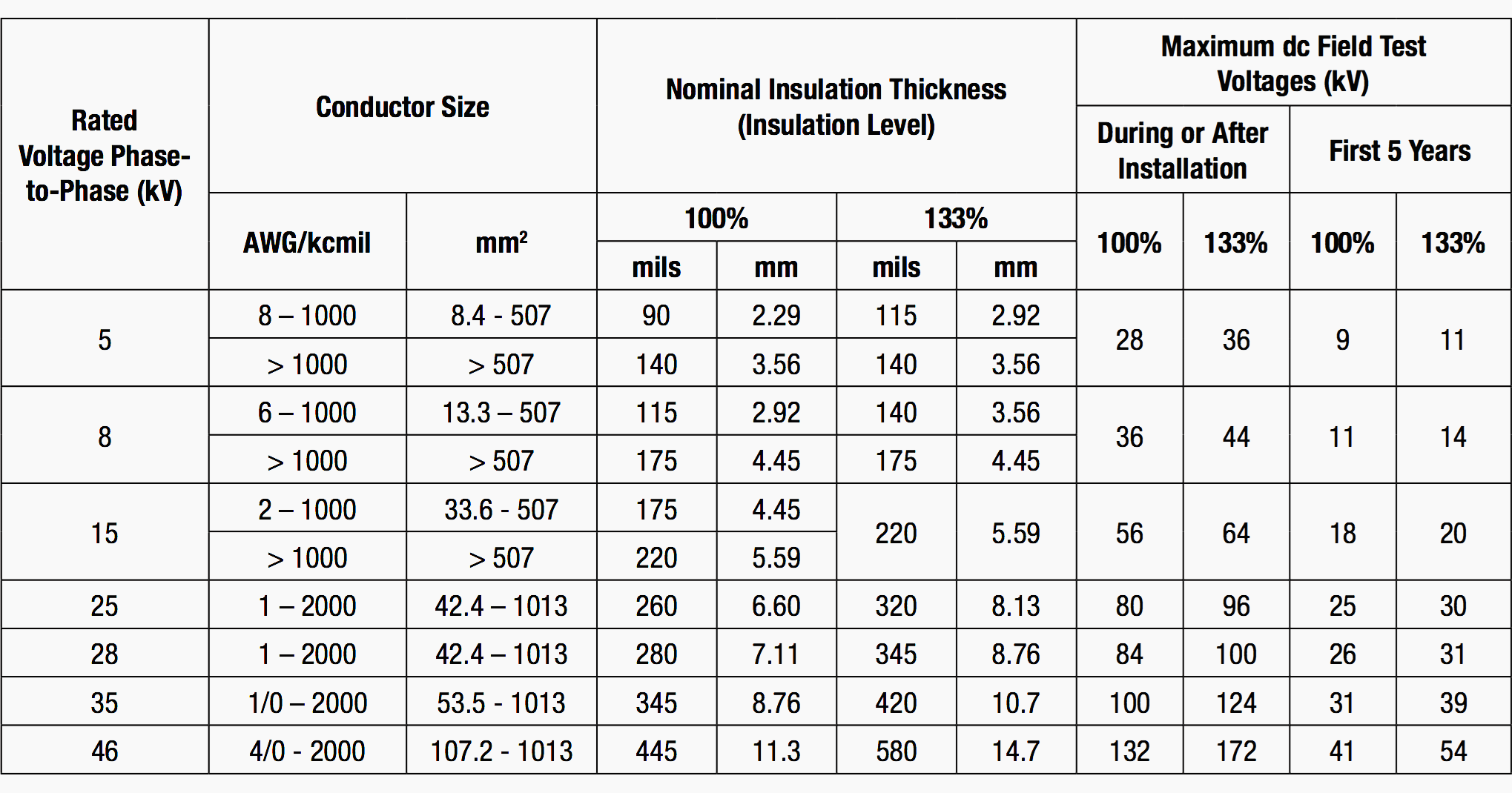
After installation and before the cable is placed in regular service, the test voltages specified in Table c.1. should be applied for 15 consecutive minutes. Record the leakage current at one minute intervals for the duration of the test.
Table c.1. – ICEA dc Field Test Voltages
ICEA S-97-682 Utility Shielded Power Cables Rated 5,000-46,000 Volts
Go back to Hi-Pot DC testing procedures ↑
c.2. Maintenance testing
At any time during the warranty period, the cable circuit may be removed from service and tested at a reduced voltage (normally 65% of the original acceptance value) for 5 consecutive minutes. Record the leakage current at one minute intervals for the duration of the test.
Some power cable users, particularly in the continuous process industries, have adopted a program of testing circuits during planned outages, preferring breakdowns during testing rather than experiencing a service outage during regular operations.
It is nearly impossible to recommend test voltage values for maintenance testing without having a history of the cable circuit. An arbitrary test voltage level could result in a cable failure in a circuit that would otherwise have provided long trouble-free service at normal operating ac voltage.
Periodic off-line partial discharge testing at very low frequencies (VLF) is a diagnostic method for monitoring the insulation degradation of medium voltage cable. This type of testing is discretionary and generally not recommended.
Go back to Hi-Pot DC testing procedures ↑
3. Common testing problems
Some common problems that may be encountered during testing are listed below.
Extra leakage current:
- Failure to guard against corona
- Failure to clean insulation surface
- Failure to keep cable ends dry
- Failure to provide adequate clearance to ground
- Failure to isolate the cable from other equipment
- Improper shield termination
Erratic readings:
- Fluctuating voltage to test set
- Improper test leads
Environmental influences:
- High relative humidity
- Dampness, dew, fog
- Wind, snow
Go back to Hi-Pot DC testing procedures ↑
4. Fault locating
Time Domain Reflectometer (TDR) units are portable commercially available devices which can be used in the field to locate some types of conductor breaks or shorts. They connect to the end of the cable and echo back when an open, short or tap is encountered. The device can usually locate faults within ± 2 in. of the cable length.
Nevertheless, the method is nondestructive and is used successfully on faults having characteristics within the capabilities of the method. Note that the conductor may be in a low voltage or medium voltage cable, shielded or non-shielded, or it may even be the shield.
Go back to Hi-Pot DC testing procedures ↑
5. Testing checklist
- Safety – Follow test equipment supplier’s instructions. Operators should be familiar with the test equipment. Stay clear of energized cable ends. Ensure that shields are grounded! Insulated conductors are capacitors.
- Voltages – Check cable and termination manufacturer’s guidelines.
- Records – Keep detailed records and provide copy to owner.
Go back to Hi-Pot DC testing procedures ↑
Reference // Cable Installation Manual for Power and Control Cables by General Cable
Related electrical guides & articles


Edvard Csanyi
Hi, I'm an electrical engineer, programmer and founder of EEP - Electrical Engineering Portal. I worked twelve years at Schneider Electric in the position of technical support for low- and medium-voltage projects and the design of busbar trunking systems.I'm highly specialized in the design of LV/MV switchgear and low-voltage, high-power busbar trunking (<6300A) in substations, commercial buildings and industry facilities. I'm also a professional in AutoCAD programming.
Profile: Edvard Csanyi

I conducted 33kV cable rated high pot testing I sometimes experience trip my DC Diectric test set applied voltage DC 57kV at 15 mins due to not properly guarded and sleeve those other cores if say, I am undertest phase-A I shileded Phases B-C to Earth once the other end not properly PVC sleeve during this testing it will cause to trip the DC kit. Now, I got reading every 0-min, 5-mins 10-mins and lastly 15-mins… the most reading is micro-Omhmer value. just share as per DGS-UE-020
We are needed
Hipot test check list
At the site, Hi-potential test for 33kV Cable is on going and I need help of the technical advice regarding the elastimold.
1. Concerns during Hi-Pot Test
During the Hi-pot Test upto 76kV DC (for 15 minutes), the cable has been tripped continuously before reach to 15minutes. (as per IEC 60502-2, 2014)
Among total 12Nos 33kV Cables, only 4Nos Cables are passed the Hi-Pot Test and others failed.
2. Applied Raychem Elastmold Termination kit.
3. Technical Advice Request.
As I know cable hi-pot test shall be applied for cable itself, not with termination kit.
Cable test without elastimold was ok.
But Client want to test with Elastimold termiantion head.
In this case several times trip was happened around 69~70kV.
The point I want to have advice is whether elatimold shall be included or not for cable hi-pot.
Termination kit can be applicable for megger test only I think.
Thank you..
i would like to get all reply on the above mentioned comments
Dear Sir
I ask your price for a hypotest cable to test 11kV AC / DC cables
Dear sir,
Have a good day.
I need your help and support , I have 13.8 KV cable energized from 10 years and we made joint in that cable and we need to perform HI-POT test on it . so I need from you to suggest to me suitable voltage to apply on the cable when we use AC or DC voltage and the aging of the cable it will be very important to take in consideration. If you can tell me the formula for the applied voltage which depend on aging of cable .
Please I need your support .
Is it usually or not to calculate the necessary size of the medium cables (6-6.6 kV) , for value of short circuit of the bus-bars from where these are connected ? It is about cables in a classical power station , connected from unit service or general service.
Thank you in advance for your answers.
Agreed with Gary Catlin. If the published date of this article was 1990s or earlier, I think there was no problem with that! DC Hipot is still OK test for insulators, or oil filled cables. But non of the new standards recommend it for polymeric cables especially XLPE.
I suggest EEP to consider revising this or ask folks with cable testing practice (NEETRAC, IEEE ICC, etc) to clarify this to avoid misleading the readers.
Yes Gary I thought the preferred “low stress” method was to use a partial discharge test method which is used by cable manufacturers to ensure their insulation is solid and free from voids or other contaminants. In the field there are several companies using monitoring to predict or warn of early insulation failure while the system is live.
It seems that your author is contradicting advice of IEEE 400 (2012), IEC 60502 (2014), Neetrac and many other reputable independent organisations all of which do not recommend DC for testing of extruded cables and which clearly outline the many shortcomings of DC testing. His advice is not referenced except for a table in a cable manufacturing standard which has little information on field testing.
I must question the authors experience or assume that there is some commercial bias.