
Estimated Study Time: 29 minutes
Cable technology
Differences between the electrical characteristics of overhead transmission lines and high voltage AC cables are fundamental and must be considered. This article gives a brief introduction to cable technology, with focus on the topics which must be considered when designing a protection system for a mixed conductor circuit which consist of both cable and overhead line.
 High Voltage Cables In a Nutshell (Technology, Bonding, Installation and Service) - photo credit: New River Electrical Corporation
This article will also touch the fault statistics of underground cable circuits and overhead lines. This is an important input for the auto-reclose policy applied to mixed conductor circuits.
Let’s make the contents:
- Cable types
- Cable accessories
- Metallic sheath of the cable
- Bonding techniques
- Cable arrangement and laying techniques
- Service experience / Fault statistics
1. Cable types
For 110 kV and higher cable systems, there are today two dominant technologies for the insulation – polymeric and paper.
Insulated cables for 110 kV and higher system voltages have been used since the 1920s with oil impregnated paper insulation.
Table 1 below gives the repartition between these two technologies in 2005 of 32 917 circuit km of land cable from 60 kV and up. This table is extracted from Cigre WG B1.10: brochure 379: Update of service experience of HV underground and submarine cable systems (April 2009).
According to this survey, 61 % of the cables are polymeric cable and 39 % paper insulated cables.
Table 1 – Repartition between polymeric and paper insulated cables
| Voltage range | 60-109 kV | 110-219 kV | 220-314 kV | 315-500 kV | Total |
| Total length [km] | 17 978 | 9 483 | 4 457 | 999 | 32 917 |
| Polymeric [%] | 78 | 45 | 34 | 25 | 61 |
| Paper [%] | 22 | 55 | 66 | 75 | 39 |
In these 2 technologies, there are several variants. The most important ones are XLPE (extruded cross linked Polyethylene) for polymeric and SCFF (self-contained fluid filled) for paper.
In the years 2000 to 2005 almost all installed AC cables have being XLPE or SCFF with XLPE being the preferred technology.
In this period 90 % of all cables installed at voltages below 220 kV were of the XLPE type. 40 % of new installations at levels above 220 kV were of the SCFF type.
1.1. Paper insulated Cables
1.1.1. High-pressure fluid-filled (HPFF) pipe cables
This type of cable is used mainly in North America and the former USSR countries. It has been used in the United States in the 200 to 275 kV range since the late 1950s.
The first 345 kV HPFF cable application was designed in 1991. HPFF cables are now in service for voltage levels up to 550 kV.
The insulation material is impregnated paper. The pipe is coated externally to prevent corrosion. The permittivity, dielectric loss angle and thermal resistivity of the dielectric are essentially the same as for SCFF cables.
The cable capacity can be increased by pumping oil through a heat exchanger or a refrigeration unit.
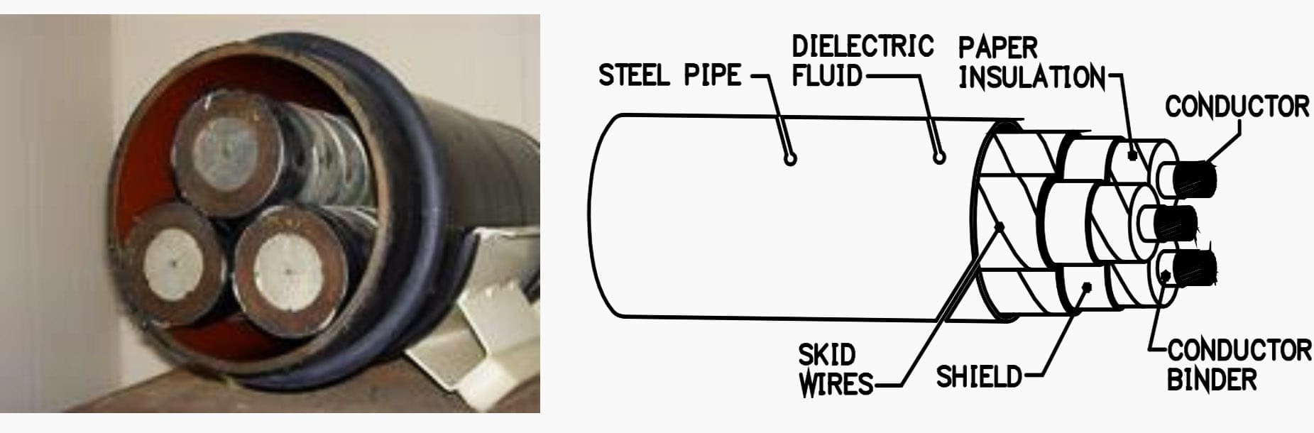
Alternatively, the pipe may be pressurized with nitrogen. This type of construction is called High Pressure Gas-Filled (HPGF) cable. However, this kind of high pressure cables is limited to a maximum voltage level of 138 kV.
The steel pipe can be driven into saturation which will cause a non-linear relationship between the current in the conductors (including the steel pipe) and the voltage drop along the conductors.
1.1.2. Self-contained fluid-filled (SCFF) cables
Originally the cable was called Self-contained oil filled (SCOF). However, the name was changed during the time. Today most used impregnations are synthetic fluids.
SCFF is the predominant transmission cable in all parts of the world, even though the increasing number of XLPE applications for voltage levels higher than 240 kV.
The cable is filled with fluid. Special tank architecture must be provided for fluid expanding due to temperature rises during load or short circuit conditions. To ensure a full impregnation at all time the core of the cable must be hollow.
This allows fluent fluid during temperatures changes while current level variations.
The normal size range of the core is from 120 to 2500 mm2 for single core cable, and from 120 to 630 mm2 for 3-core cable. For application with voltage levels higher than 150 kV only single core cables are available.
Due to increased dielectric loss with higher voltage levels the maximum current ratio decreases accordingly. Therefore a new insulation material, paper laminated with polypropylene (PPL), has been developed. This material ensures less dielectric loss and is economical for voltages from 275 kV and upward.
Traditionally all SCFF cables were designed with lead sheaths. Today a significant number of these cables are sheathed with aluminium material. This has mainly economic reasons – there is no influence to the cable behaviour.
Table 2 – Typical values for cables direct laid with depth 900 mm, flat formation (single core) spacing 230 mm between Centers. Ground temperature 15o° C. Soil thermal resistivity 1.2 k m/w. Conductor operating temperature 90o° C.
1.2. Polymeric cables
XLPE cables for voltage levels higher than 100 kV were introduced in the early 1970s. A few years later, polymeric cables for higher voltage levels (230 kV and above) becomes available as well.
The technology is now extensively used in Europe, the Middle-East and Asia. At the end of 2005 45% of the cable applications for voltage levels between 110 to 219 kV were designed with polymeric types. 25% of the cable applications for 315 to 500 kV are described at the same time.
The actual trend is the increasingly use of polymeric cables for all voltage levels.
Thermoplastic Polyethylene (PE) and cross-linked polyethylene (XLPE) have been the most commonly used polymeric insulation, while ethylene propylene rubber (EPR) has had limited use up to 150 kV.
XLPE have an advantage over PE as it can be operated at 90° C compared to 70° C for LDPE (Low density Polyethylene) and 80° C for HDPE (High density Polyethylene). Composition of a typical XLPE cable (see figure 3):
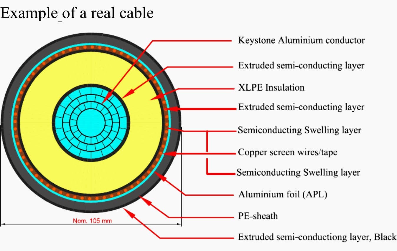
The cable is composed of:
- Conductor – copper or aluminium.
- Semi-conductor layer around the conductor to provide an uniform electric field.
- XLPE insulation.
- Metallic sheath composed of a copper wire screen and an aluminium, copper or lead sheath. The purpose is to protect conductor and insulation against external damage. It acts as an electrical screen and also conducts the fault current to earth in case of an internal fault.
An example is shown in figure 4 below.
Edvard Csanyi
Hi, I'm an electrical engineer, programmer and founder of EEP - Electrical Engineering Portal. I worked twelve years at Schneider Electric in the position of technical support for low- and medium-voltage projects and the design of busbar trunking systems.I'm highly specialized in the design of LV/MV switchgear and low-voltage, high-power busbar trunking (<6300A) in substations, commercial buildings and industry facilities. I'm also a professional in AutoCAD programming.
Profile: Edvard Csanyi
