Search

Premium Membership ♕

Save 10% on Pro Membership Plan with coupon DEC10 and study specialized LV/MV/HV technical articles and papers.

Home / Technical Articles / 31 Common Household Circuit Wirings You Can Use For Your Home (2)

1st part | 2nd part | 3rd part
31 Common Household Circuit Wirings You Can Use For Your Home (2nd part)

Household Circuit Wirings

The list of the next ten household circuit wirings:

  1. Double receptacle circuit with shared neutral wire (receptacles alternate circuits)
  2. Double receptacle small-appliance circuit with GFCIs & shared neutral wire
  3. Double receptacle small appliance circuit with GFCIs & separate neutral wires
  4. 120/240V range receptacle
  5. 240V Baseboard heaters, thermostat
  6. Dedicated 120v computer circuit, isolated-ground receptacle
  7. 240V appliance receptacle
  8. Ganged single-pole switches controlling separate light fixtures
  9. Ganged switches controlling a light fixture and a vent fan
  10. Three-way switches & light fixture (fixture between switches)

11. Double receptacle circuit with shared neutral wire (receptacles alternate circuits)
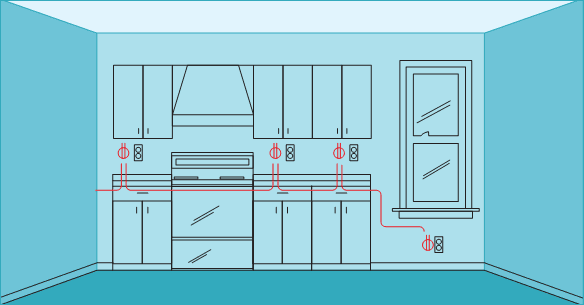
Double receptacle circuit with shared neutral wire (receptacles alternate circuits)

This layout features two 120 V circuits wired with one three-wire cable connected to a double-pole circuit breaker. The black hot wire powers one circuit. The red wire powers the other. The white wire is a shared neutral that serves both circuits.

When wired with 12/2 and 12/3 cable and receptacles rated for 20 A, this layout can be used for the two small-appliance circuits required in a kitchen.

Remember to use a GFCI circuit breaker if you use this circuit for kitchen counter top receptacles.
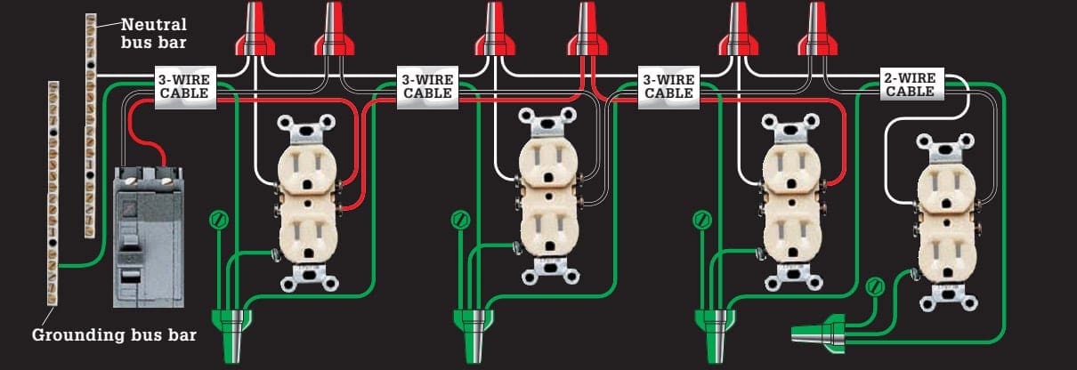
This layout features two 120-volt circuits wired with one three-wire cable connected to a double-pole circuit breaker
This layout features two 120 V circuits wired with one three-wire cable connected to a double-pole circuit breaker

Go back to Circuit Wirings ↑

12. Double receptacle small-appliance circuit with GFCIs & shared neutral wire

Double receptacle small-appliance circuit with GFCIs & shared neutral wire

Use this layout variation of circuit wiring 10 to wire a double receptacle circuit when code requires that some of the receptacles be GFCIs. The GFCIs should be wired for single-location protection (see circuit wiring 2).

Requires three-wire and two-wire cables.
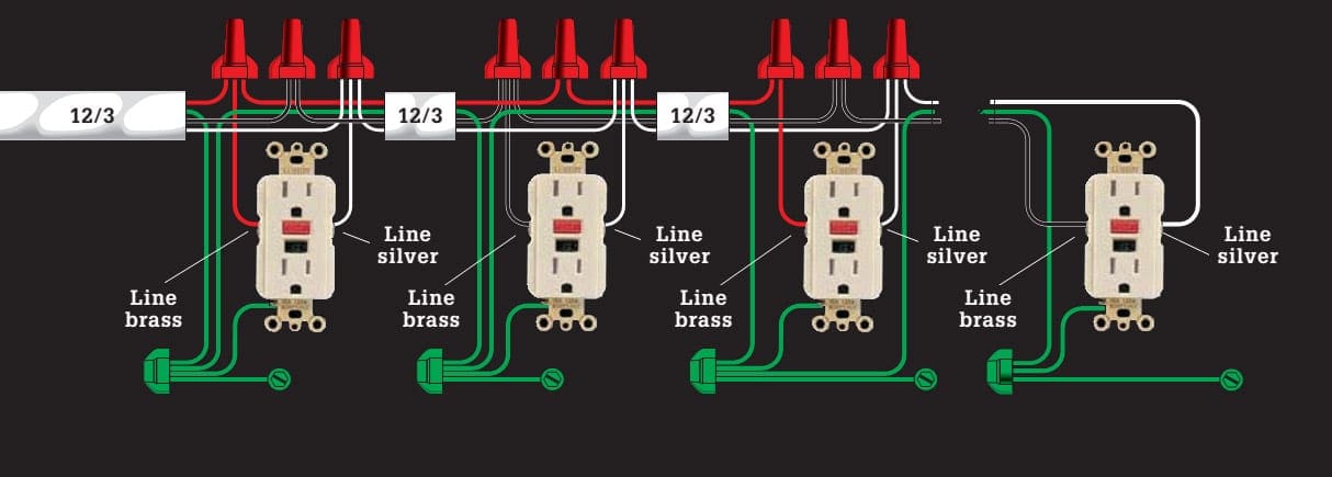
Use this layout variation of circuit wiring 10 to wire a double receptacle circuit

Go back to Circuit Wirings ↑

13. Double receptacle small appliance circuit with GFCIs & separate neutral wires
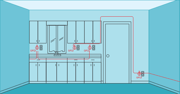
Double receptacle small appliance circuit with GFCIs & separate neutral wires

If the room layout or local codes do not allow for a shared neutral wire, use this layout instead. The GFCIs should be wired for single-location protection (see circuit wiring 2).

Requires two-wire cable.
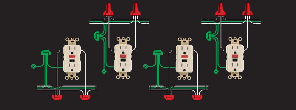
If the room layout or local codes do not allow for a shared neutral wire, use this layout instead

Go back to Circuit Wirings ↑

14. 120/240V range receptacle

120/240V range receptacle

This layout is for a 40- or 50 A, 120/240 V dedicated appliance circuit wired with 8/3 or 6/3 cable, as required by code for a large kitchen range. The black and red circuit wires, connected to a double-pole circuit breaker in the circuit breaker panel, each bring 120 volts of power to the setscrew terminals on the receptacle.

The white circuit wire attached to the neutral bus bar in the circuit breaker panel is connected to the neutral setscrew terminal on the receptacle.

This layout is for a 40- or 50-amp, 120/240-volt dedicated appliance circuit wired with 8/3 or 6/3 cable
This layout is for a 40- or 50 A, 120/240 V dedicated appliance circuit wired with 8/3 or 6/3 cable

Go back to Circuit Wirings ↑

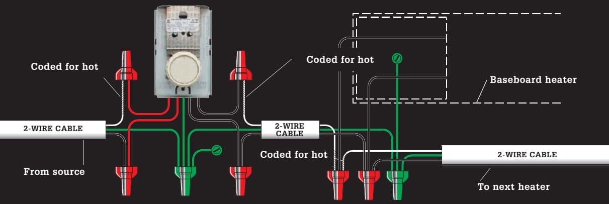
15. 240V Baseboard heaters, thermostat

240V Baseboard heaters, thermostat

This layout is typical for a series of 240 V baseboard heaters controlled by a wall thermostat. Except for the last heater in the circuit, all heaters are wired as shown below. The last heater is connected to only one cable.

The sizes of the circuit and cables are determined by finding the total wattage of all heaters.

Requires two-wire cable.

This layout is typical for a series of 240-volt baseboard heaters controlled by a wall thermostat
This layout is typical for a series of 240 V baseboard heaters controlled by a wall thermostat

Go back to Circuit Wirings ↑

16. Dedicated 120v computer circuit, isolated-ground receptacle

Dedicated 120v computer circuit, isolated-ground receptacle

This 15 A isolated-ground circuit provides extra protection against surges and interference that can harm electronics. It uses 14/3 cable with the red wire serving as an extra ground ing conductor. The red wire is tagged with green tape for identification.

It is connected to the grounding screw on an isolated-ground receptacle and runs back to the grounding bus bar in the circuit breaker panel without touching any other house wiring.
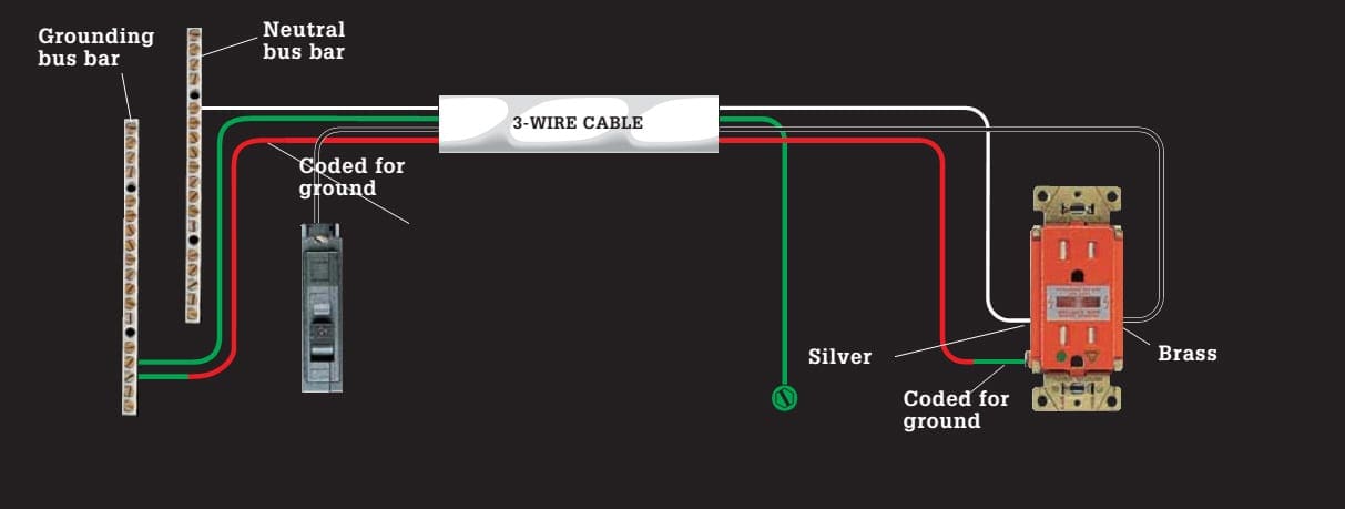
This 15-amp isolated-ground circuit provides extra protection against surges and interference that can harm electronics
This 15 A isolated-ground circuit provides extra protection against surges and interference that can harm electronics

Go back to Circuit Wirings ↑

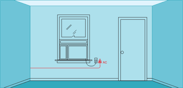
17. 240V appliance receptacle

240V appliance receptacle

This layout represents a 20 A, 240 V dedicated appliance circuit wired with 12/2 cable, as required by code for a large window air conditioner. Receptacles are available in both singleplex (shown) and duplex styles.

The black and the white circuit wires connected to a double-pole breaker each bring 120 volts of power to the receptacle (combined, they bring 240 volts).

The white wire is tagged with black tape to indicate it is hot.
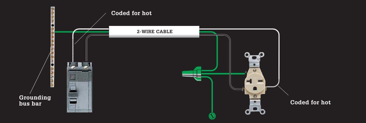
This layout represents a 20-amp, 240-volt dedicated appliance circuit wired with 12/2 cable
This layout represents a 20 A, 240 V dedicated appliance circuit wired with 12/2 cable

Go back to Circuit Wirings ↑

18. Ganged single-pole switches controlling separate light fixtures

Ganged single-pole switches controlling separate light fixtures

This layout lets you place two switches controlled by the same 120 V circuit in one double-gang electrical box. A single-feed cable provides power to both switches. A similar layout with two feed cables can be used to place switches from different circuits in the same box.

Requires two-wire cable.
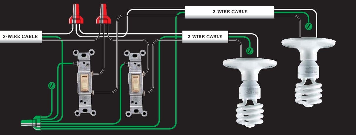
This layout lets you place two switches controlled by the same 120-volt circuit in one double-gang electrical box
This layout lets you place two switches controlled by the same 120 V circuit in one double-gang electrical box

Go back to Circuit Wirings ↑

19. Ganged switches controlling a light fixture and a vent fan
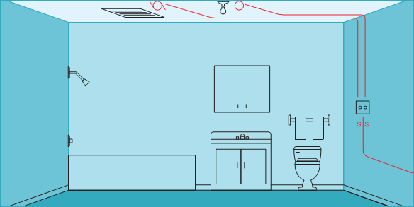
Ganged switches controlling a light fixture and a vent fan

This layout lets you place two switches controlled by the same 120 V circuit in one double-gang electrical box. A single-feed cable provides power to both switches.

A standard switch controls the light fixture, and a time-delay switch controls the vent fan.
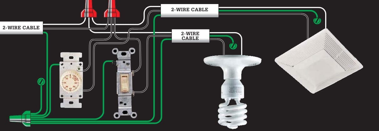
This layout lets you place two switches controlled by the same 120-volt circuit in one double-gang electrical box
This layout lets you place two switches controlled by the same 120 V circuit in one double-gang electrical box

Go back to Circuit Wirings ↑

20. Three-way switches & light fixture (fixture between switches)
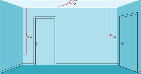
Three-way switches & light fixture (fixture between switches)

This layout for three-way switches lets you control a light fixture from two locations. Each switch has one common screw terminal and two traveler screws. Circuit wires attached to the traveler screws run between the two switches, and hot wires attached to the common screws bring current from the power source and carry it to the light fixture.

Requires parallel runs of 2-wire cable.
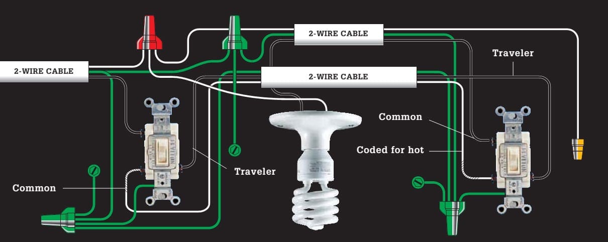
This layout for three-way switches lets you control a light fixture from two locations

Go back to Circuit Wirings ↑


1st part | 2nd part | 3rd part

Reference // The Complete Guide to Electrical Wiring (Current with 2014–2017 Electrical Codes) – Black+Decker

Premium Membership

Get access to premium HV/MV/LV technical articles, electrical engineering guides, research studies and much more! It helps you to shape up your technical skills in your everyday life as an electrical engineer.
More Information
Edvard Csanyi - Author at EEP-Electrical Engineering Portal

Edvard Csanyi

Hi, I'm an electrical engineer, programmer and founder of EEP - Electrical Engineering Portal. I worked twelve years at Schneider Electric in the position of technical support for low- and medium-voltage projects and the design of busbar trunking systems.

I'm highly specialized in the design of LV/MV switchgear and low-voltage, high-power busbar trunking (<6300A) in substations, commercial buildings and industry facilities. I'm also a professional in AutoCAD programming.

Profile: Edvard Csanyi

Leave a Comment

Tell us what you're thinking. We care about your opinion! Please keep in mind that comments are moderated and rel="nofollow" is in use. So, please do not use a spammy keyword or a domain as your name, or it will be deleted. Let's have a professional and meaningful conversation instead. Thanks for dropping by!

5  +  five  =  

Learn How to Design Power Systems

Learn to design LV/MV/HV power systems through professional video courses. Lifetime access. Enjoy learning!

EEP Hand-Crafted Video Courses

Check more than a hundred hand-crafted video courses and learn from experienced engineers. Lifetime access included.
Experience matters. Premium membership gives you an opportunity to study specialized technical articles, online video courses, electrical engineering guides, and papers written by experienced electrical engineers.