The residual current device (rcd) is used to detect earth fault currents and to interrupt supply if an earth current flows. The main application is to prevent electrocution but RCDs can also be used to protect equipment, especially against fire. The earth fault currents that operate an rcd can range from 5mA up to many amperes. For typical domestic applications the typical trip current would be 30 mA. The RCD can be opened and closed manually to switch normal load currents, and it opens automatically when an earth fault current flows which is about 50 per cent or more of the rated tripping current.
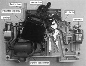
The main features of an rcd are shown in Fig. 1. The key component is a toroidal transformer, upon which the load current (live) and return current (neutral) conductors are wound in opposite directions. The toroid also carries a detecting winding. If no earth fault current is flowing, then the load and return currents are equal. In this case the mmfs generated by the load and return current windings are equal; there is no resultant flux in the toroid and the detecting winding does not generate any current.
When a fault current flows there is a difference between the load and return currents which generates a resultant flux in the toroid and induces a current in the detecting winding.

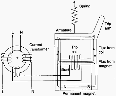
The current generated in the detecting winding operates a relay which opens the main contacts of the RCD. The detecting winding has to produce from a very small output, sufficient power to operate the tripping mechanism. Two alternative methods are used. In the first method, the output signal from the detecting coil is electronically amplified and the second method uses a polarized relay operating on a sensitive mechanical trip mechanism. The operation of a polarized trip relay is based on the magnetic output of a small coil nullifying the field from a permanent magnet, causing the release of an armature. The basic operation is illustrated in Fig. 2.
The operation of an rcd has here been described for single-phase operation, but it may also be applied in a three-phase application where typically it might be used in a light industrial system for protection against fire. There are two arrangements of a three-phase rcd. Either the three phases are wound around a current transformer, or the three phases and the neutral are wound onto a balancing transformer.
The RCD has only limited breaking capacity and it is not a replacement for overcurrent protection devices such as the MCB. The residual current breaker with overcurrent (RCBO) is now available; this is an rcd with an overcurrent tripping mechanism and enhanced contacts to cope with interruption of fault conditions.
RCDs are designed and tested according to the requirements of IEC 1008 and IEC 1009.


Shouldn’t the load/live and neutral conductors be wound the same way on the sense toroid? The current is already flowing in opposite directions, so being laid up in parallel the equal-but-opposing currents would produce equal-but-opposing mmf, no net flux. If they are wound in opposite directions, the result would be net flux proportional to the load current
Hi, Our domestic supply is protected by an RCD. When we came back from a weeks holiday last year we found that the power was off and our freezers were full of mush, i.e defrosted food. Apparently, there was an electrical storm on the Monday night which must have tripped the RCD and there was nobody there to reset it. Is there a safety device available that will reset itself after a short period?
You need to investigate why exactly it was the RCD that was tripped and not a circuit breaker. Typically, in case of power failures involving, say, overvoltage or undervoltage, the piece of kit that takes care of it is the power relay. These relays typically do have a timeout, meaning that after they are tripped, when conditions are good again the relay will wait a certain amount of time (since immediate off-on is bad for some equipment, most notably refrigerators) and will then turn itself on.
An alternative, and somewhat better solution, is to use a smart home monitoring system that simply sends you an email or SMS when power is down. More often than not, electrical systems need to be recovered by qualified professionals, so if you’re not around at least you can get someone nearby to come and look for potential problems.
You people are doing a great job keep it up.
please can you add wiring and installing of panels diagrams and procedural’s to equip those of as who are now learning. Thank You
What is RESIDUAL CURRENT ? How it is working in RCCB or RCBO or RCD
The CE requirements are different than here in North America. What are the CE standards that require RCD protection for the main circuit breaker (incommer) of dedicated control panels that feed power to an medical X-ray, CT or MRI? What are the required RCD trip levels. In the past we have had requests for different trip levels of 30 and 100ma.
In terms of response levels, the general-purpose sensitivity is 30mA. However, for wet rooms such as bathrooms, kitchen, outdoor use (say socket on a balcony) the sensitivity of 10mA is recommended (but not actually mandated in many standards). Furthermore a very high sensitivity (100mA or 300mA) that is used as a first-step (also called anti-fire) differential protection. In an apartment building it might appear in, say, a panel on a particular floor. The goal here is to protect the incoming cable, protect the connecting lines where differential protection is not installed, and as an extra level of protection if there are RCDs downstream that do not work for some reason.
Naturally, you don’t want this to trip before/at the same time as the sensitive RCDs, which is why both the sensitivity and response times need to differ by a factor of 3. For this to work not only do you need high sensitivity, you also need the RCD to work with a time delay.
Sir I am a little bit confused about tripping operation in three phase networks . as I read, it detecs unbalance current between live & neutral conductor. so at which principle it will work for three phase network.