
Estimated Study Time: 40 minutes
Medium Voltage Switchgear
Let’s discuss the most critical factors that influence the correct configuration of medium-voltage switchgear. As you will see below, for the most common applications of MV switchgear, there are at least six main categories that are very important in the design of future power distribution.
 Configuration of medium voltage switchgear: The most critical factors
As you will see, these categories are MV network characteristics, protection, measurement and metering concepts, the operating principle and number of infeeds, installation location and accessibility, environmental conditions, and requirements for operating procedures.
The most essential industry-specific application requirements for medium-voltage switchgear, such as switching-duty-capacity, switching frequency of the loads, switchgear modifications or extensions, are also covered.
Take your coffee, and let’s get on!
- MV network characteristic values:
- Line Protection, measurement and metering concepts:
- Infeed types
- Operating sites:
- Environmental conditions:
- Industry-specific application:
- Operating procedures:
- BONUS (PDF) 🔗 Download ‘Protection Study for 132kV, 33kV and 11/6.6kV Primary Substations’
1. MV network characteristic values
1.1 Line voltage
This determines the rated voltage of the switchgear, switching devices, and other installed components. The determining factor here is the maximum line voltage at the upper tolerance limit.
Assigned configuration criteria for switchgear:
- Rated voltage Ur (or Us)
- Rated insulation level Ud (or Upn)
- Rated primary voltage of voltage transformers Upr and surge arrester – where applicable
Table 1 – Rated voltage of the primary circuit – General case
1.2 Short-circuit current
This is characterized by the variables peak current Ip (peak value of the initial symmetrical short-circuit current) and sustained short-circuit current Ik. The required short-circuit current level in the network is specified by the dynamic behaviour of the loads and the quality of the energy, which must be maintained, and determines the making, breaking, and withstand capacity of the switchgear.
Note that the ratio of the peak current to the sustained short-circuit current in the network can be significantly greater than the standard factor Ip/Ik = 2.5 at 50 Hz (or 2.6 at 60 Hz) according to which the circuit-breakers and switchgear are designed.
Assigned configuration criteria for switchgear:
- Main and earthing circuit:
- Rated peak current Ip
- Rated short-time current Ik
- Switchgear:
- Rated short-circuit making current Ima
- Rated short-circuit breaking current Isc
- Current transformer:
- Rated dynamic current Idyn
- Rated short-time thermal current Ith
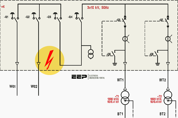
Figure 1 – An example of short circuit in 10kV medium-voltage switchgear
1.3 Normal current and load flow
The normal current refers to the current paths of the infeeds, busbar(s), and load feeders. The current is also subdivided due to the physical arrangement of the switchgear panels with the effect that different rated current values can be found in sequence along the conducting path (the currents in busbars and feeders are normally different).
Reserves must be planned for the value of the rated normal current:
- In accordance with the ambient temperature;
- For the planned overload;
- For temporary overloads in the event of faults.
Assigned configuration criteria for switchgear:
- Rated current of busbar(s) and feeders
- Number of cables for each conductor in the switchgear panel (parallel cables)
- Rating of the current transformers
Figure 2 – Initial Load Flow Analysis in ETAP
1.4 Neutral point earthing
The type of neutral point earthing used, insulated / resonant earthed with an arc suppression coil (Petersen coil) / (temporarily) resistively earthed / solidly (directly) earthed – governs the behaviour of the line voltage when switching operations are carried out or if a earth fault occurs in the network as well as the characteristics of the earth fault currents.
Assigned configuration criteria for switchgear:
- Insulation level of the equipment assigned to the rated voltage Ur
- Choice of switchgear
- Rating and damping of voltage transformers
- Design of current transformers and protection relays for earth fault detection
- Rating of surge arresters
Figure 3 – MV Neutral Earthing Methods and Their Applications
1.5 Underground / overhead lines
The network type governs insulation coordination and which overvoltage protection measures need to be taken. In overhead systems, powerful overvoltages can be caused by a lightning strike, while only weak switching overvoltages generally occur in underground networks. Overvoltages from overhead systems can reach switchgear indirectly or via a transformer.
These connecting points must be taken into account and checked to determine whether surge arresters are needed.
Assigned configuration criteria for switchgear:
- Selection and rating of circuit-breakers
- Insulation level
- Use and rating of surge arresters
Figure 4 – Transient stability analysis enables engineers to accurately simulate and analyze power system dynamics and transients via system disturbances and other events
1.6 Overvoltage protection
If the expected voltage stresses exceed the insulation level of the equipment, insulation coordination requires overvoltage protection. This can apply, for example:
- When external overvoltages can be expected as a result of lightning strikes;
- When (multiple) earth faults occur frequently;
- High transient overvoltages may occur as a result of switching operations;
- When, in the interests of economy, certain equipment (e.g. motors, resin-encapsulated / dry-type transformers) is rated for lower insulation levels than the other network components.
Overvoltage protection is also used as a general precaution to minimize the risk of failure and to protect equipment against any form of overvoltage. It is generally used for very large motors or transformers that are not only expensive and difficult to procure but also incur high costs if they fail.
Overvoltage protection systems normally comprise surge arresters. In certain cases, surge capacitors or resistance-damped surge capacitors (RC elements) are also required. Switchgear must be checked to determine whether overvoltage protection is required, whether protection measures have already been taken, or whether existing protection devices need to be upgraded.
Assigned configuration criteria for switchgear:
- Insulation level
- Check for “critical” switching duties
- Application and rating of the surge arresters, space for installtion and possibility for the connection of external arresters
Further Study – MV/LV transformer protection against temperature rise, overloads, short-circuit & overvoltages
MV/LV transformer protection against temperature rise, overloads, short-circuit & overvoltages
1.7 Power quality (unstable loads)
The power quality refers to unwanted interference, such as voltage dips, flickers, asymmetry, harmonics etc.. These can be caused for example by rectifiers, converters, welding machines, direct-starting motors. Other loads (e.g. IT systems), however, are sensitive. To protect them, the interference is compensated as much as possible or the “stable” and “unstable” loads are distributed across sub-networks with separate infeeds.
Depending on the circuit arrangement, switchgear with single or double busbars is required.
Assigned configuration criteria for switchgear:
- Single/double busbar:
- Bus section panel
- Bus coupler unit
- Rated normal current (busbar)
- Rated short-circuit currents
Figure 5 – Two interconnected double busbars

2. Line Protection, measurement and metering concepts
2.1 Short-circuit protection
The line protection concept has a major influence on the switchgear that is selected and its design. The following devices can be used for short-circuit protection:
- HRC fuse (in a switch- or contactor-fuse combination)
- Instrument transformer + protection relay + circuit-breaker
Assigned configuration criteria for switchgear:
- Design: circuit-breaker or switch-disconnector unit
Figure 6 – Racking-in and racking-out operation of MV circuit breaker

2.2 Relay protection functions
Protection relays obtain their measurement signals from current and voltage transformers, which are installed in the switchgear. The range of available protection functions (e.g. inverse/definite-time overcurrent, distance/differential protection) requires current transformers whose cores can be combined in a variety of ways with different rated currents, overcurrent number, output, and class accuracy.
Voltage transformers are also provided for protection with directional control or for determining the fault location (distance protection).
The switchgear must provide a space in which these instrument transformers can be installed as well as space for the protection relays and their wiring. This may seem obvious, but it is important to remember that other components (surge arresters, multiple cable terminals etc.) also need space in the switchgear.
Figure 7 – CTs and VTs compartment in MV swtichgear
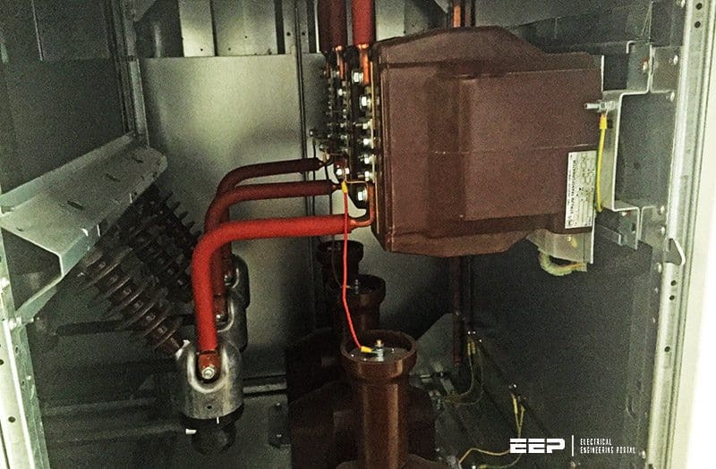
Assigned configuration criteria for switchgear:
- Installation of instrument transformers in the switchgear panel and on the busbar
- Installation of a core-balance transformer (normally cable-type current transformer, or “earth fault winding”)
- Installation of protection relays and wiring in the low-voltage compartment
Further Study – Protection Relay – ANSI Standards
2.3 Tripping times
The set tripping times (specified by means of selectivity requirements in accordance with the number of subordinate network levels and their equipment) are governed by the rated short-circuit duration of the switchgear, the current transformer, and the earthing circuit. The standards permit various rated values for the components.
For short-circuit durations of > 1 s in particular, it is important to ensure that all components are dimensioned to manage the actual short-circuit duration at the minimum.
Assigned configuration criteria for switchgear:
- Rated duration of short-circuit
- Main circuit (switchgear, disconnector, and earthing switch)
- Earthing circuit
- Current transformer
- Number and type of releases in the circuit-breaker
Further Study – The essentials of necessary auxiliary relays in tripping and control applications
The essentials of necessary auxiliary relays in tripping and control applications
2.4 Measurement and metering
Measurement and metering systems generally require separate, additional transformer cores with a different rating to that of the protection cores.
Assigned configuration criteria for switchgear:
- Room for installing transformers as well as measurement devices and meters (see Section 2.2 Relay protection functions).
2.5 Redundancy
Different protection functions can be combined in a single network branch (e.g. differential and overcurrent-time protection as backup). Depending on the degree of redundancy required, additional instrument transformers and protection devices may also have to be installed in the switchgear. Enough space must be available for these too (see above).
For contractual reasons, the same measurement device or meter may also be installed twice if contractual partners use their own devices at the point of supply (“check measurement”). This increases the number of built-in components.
Assigned configuration criteria for switchgear:
- Room for installing transformers as well as measurement devices and meters (see Section 2.2 Relay protection functions).
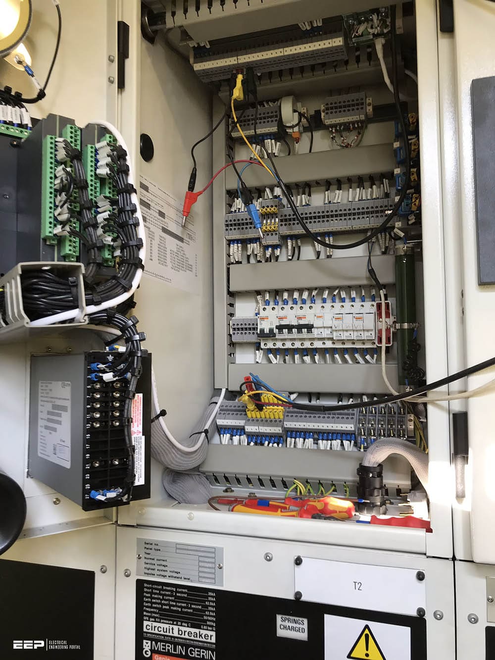
Figure 8 – Low-voltage compartment with auxiliary relays in relay protection unit in MV switchgear
3. Infeed types
The operating principle and number of infeeds are crucial for connecting the switchgear and for its rated current values. The supply from different networks, such as:
- the public network,
- in-plant generation, and
- the emergency power supply
… sometimes has to be disconnected during normal operation for safety, business, or contractual reasons. A decision must, therefore, be made regarding how the supply can be divided into busbar sections and which ones can be linked.
Assigned configuration criteria for switchgear:
- System connection:
- Single/double busbar
- Bus section panel
- Rated values of the switchgear:
- Normal current of the busbar(s)
- Peak current and short-time current
- Control, interlocks, and switchgear interlocking
- Installation of instrument transformers in the switchgear panel and on the busbar
- Room for installing the protection relays and wiring in the low-voltage compartment
Watch Video – Introduction to incoming feeder
4. Operating sites
The type of operating site can also govern the choice and rating of switchgear. Given the broad range of different influencing factors, only the key points that need to be taken into account can be described here.
4.1 Installation location
Many locations are subject to legal regulations concerning safety and health, fire protection, and environmental compatibility. This mainly applies to systems in public areas (e.g. pedestrian zones), industrial premises (offices, workshops), public buildings (high-rises, hospitals, office buildings, bars, conference centers etc.).
Special regulations also apply for nature reserves, mines, railways, and boats.
Assigned configuration criteria for switchgear:
- Design
- Internal arc fault classification
- Pressure absorber, pressure release duct
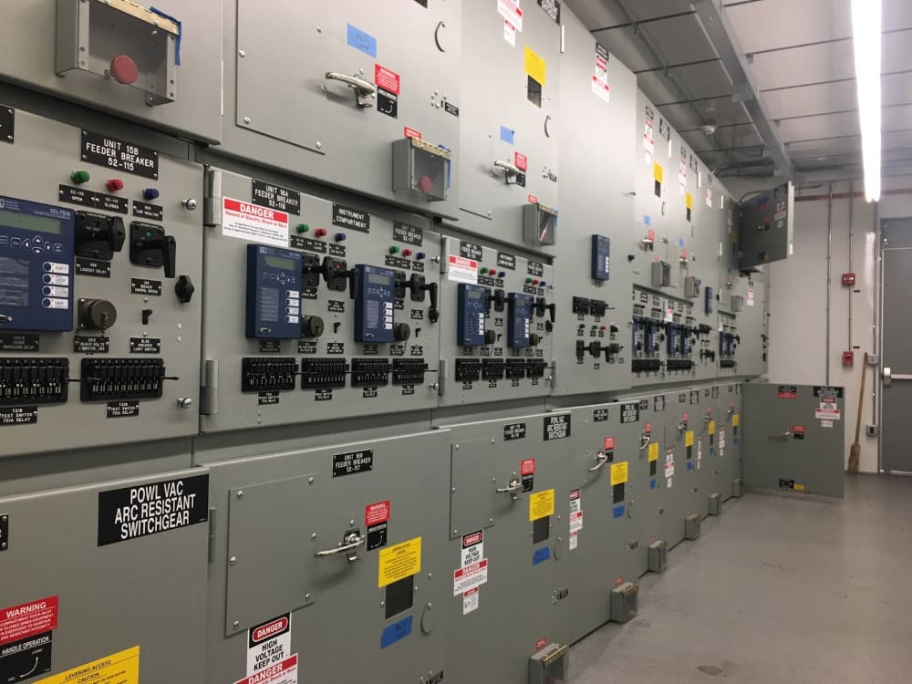
Figure 9 – Indoor metal-clad medium voltage switchgear
4.2 Accessibility of MV switchgear
The standards also take into account the different levels of accessibility of operating sites:
- Only authorized and trained personnel have access to closed electrical operating area; all other people must be accompanied.
- Operating sites in public areas can be accessed by everyone (e.g. standard for stations and switchgear in workshops).
Assigned configuration criteria for switchgear:
- Air or gas insulation
- IP degree of protection
- IK degree of protection (mechanical shock)
- Internal arc fault classification
Figure 10 – Typical incomer feeder cubicle (front, side and rear view)
4.3 Switchgear room
Certain standards, e.g. IEC 61936, and laws define specifications regarding how the system is set up in service rooms (e.g. the minimum width of operating and assembly aisles) and define the binding requirements for escape routes (e.g. width and maximum length of escape routes, preferred direction in which doors close etc.).
The service room might also contain other equipment for which operators can define their own specifications regarding free areas and setup. The switchgear must enable all requirements to be fulfilled.
Assigned configuration criteria for switchgear:
- Dimensions of the switchgear panels, in particular the panel width
- Position of door stops; opening angle of the switchgear panel doors
- Position of controls and displays/indicators (front/rear)
- Cable connection from the front or rear
- Required accessories (switching levers, tools, etc.)
- Labelling, information plates, warning signs
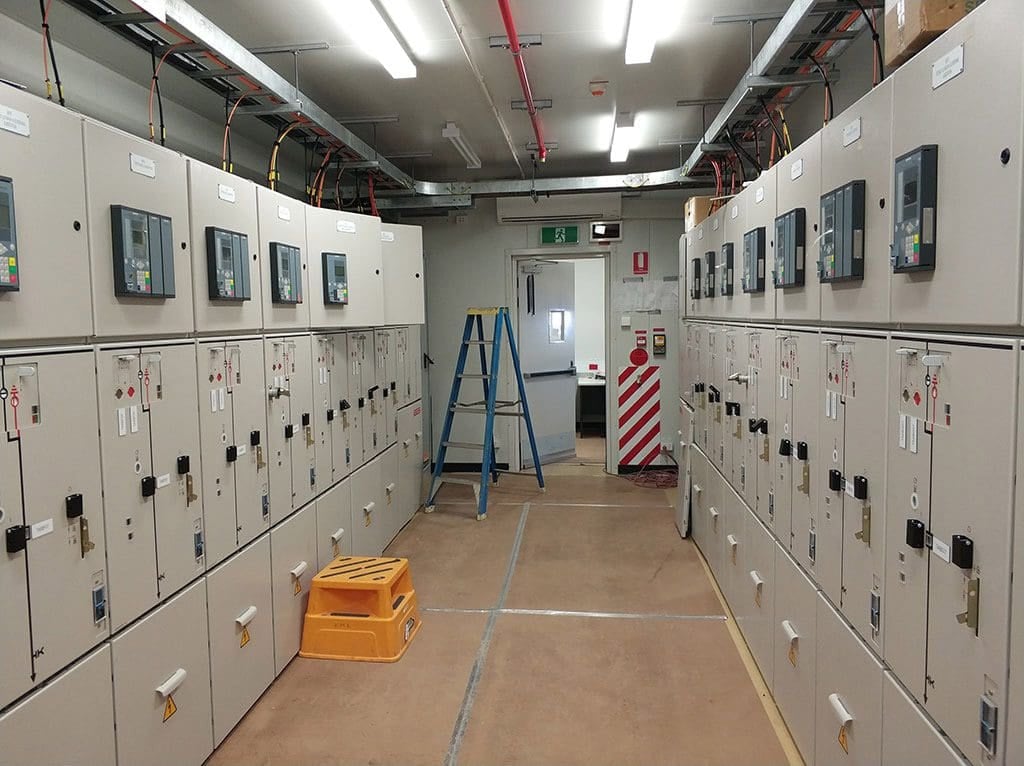
Figure 11 – MV switchgear room
4.4 Buildings
The building itself can also influence the choice of switchgear. The following aspects must be taken into account:
- The available space
- The quality of the building fabric (in existing, older buildings)
- Vent outlets in the event of an internal arc fault
Assigned configuration criteria for switchgear:
- Switchgear panel width, depth, and height
- Air or gas insulation
- Internal arc fault classification
- Pressure absorber, pressure release duct
See Section 5. Environmental conditions.
Figure 12 – Switchgear ventilation: a) Simple compartment ventilation, b) compartment ventilation with exhaust hood above the switchboard, c) ventilation with false floor, d) ventilation with recirculating cooling system

4.5 Transportation and assembly
In certain – albeit rare – cases, transportation and assembly conditions are a key selection criterion for the switchgear. Whether or not switchgear can be installed in a building depends on certain constructional factors, such as:
- The size and position of doorways
- Permissible floor loading
- Floor level
- Goods elevator
Assigned configuration criteria for switchgear:
- Size of the transportation units
- Weight of the transportation units
- Packaging (stability, weather protection if the device is in temporary storage over a long period)
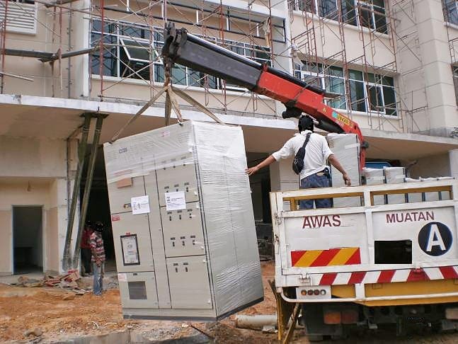
Figure 13 – Transport of low voltage and medium voltage switchgear on site
5. Environmental conditions
5.1 Ambient room conditions
Switchgear installed in service rooms can be subject to the following ambient conditions:
- Heat and humidity
- Pollution
- Dust and smoke
- Salt (near the coast or in mining)
- Corrosive gases and vapours (natural and artificial)
- Insects / small animals
Due to the infinite variety of ambient conditions at installation locations, the applicable standards only define basic requirements for “normal service conditions”. Each system much be examined individually to determine whether or not these are observed.
Assigned configuration criteria for switchgear:
- Design: air or gas-insulated switchgear
- IP degree of protection for housing (can be increased with drip-water protection if necessary)
- Type of ventilation
- Additional insulation for live and exposed components
Measures to provide protection against extreme ambient conditions can also be taken in the service room (air conditioning). In some cases, this can be more efficient than designing each individual component accordingly.
It is also important to remember that protection, measurement, and control systems are more sensitive than switchgear, which is reason enough to ensure that the minimum requirements for air quality are observed.
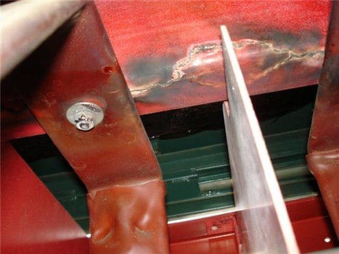
Figure 14 – Partial disharge on MV busbars caused by air pollution
5.2 Altitudes above 1000 m
The standardized insulation levels apply to normal ambient conditions at sea level. As the altitude increases, however, the air density decreases as do the insulating properties. The applicable standards take this into account and allow for a reduction of approx. 9% at altitudes of up to 1000 m.
At higher altitudes, the required insulation level must be ensured by increasing the rated voltage (with respect to sea level values).
Assigned configuration criteria for switchgear:
- Design: air or gas-insulated switchgear
- Selection of a higher rated voltage with a higher insulation level
- Use of surge arresters
Suggested Course – Surge Protection Devices (SPDs) Course: Design, Specification and Installation For True Engineers
5.3 Ambient temperature and humidity
The ambient temperature directly affects the temperature of the switchgear which, in turn, affects its current-carrying capacity. As the ambient temperature increases, the current-carrying capacity decreases (and vice versa). To compensate for this, either the rated current value must be increased or sufficient ventilation must be ensured (ventilation openings affect the IP degree of protection).
Humidity has a negative effect on the insulating properties. High levels of humidity together with sudden temperature changes can cause condensation which, in turn, drastically reduces insulation levels. To prevent this, controlled or permanent heaters can be used in conjunction with humidistats.
Assigned configuration criteria for switchgear:
- Rated normal current
- Type of ventilation
- Differentiation of IP degree of protection according to protection against ingress of solid foreign bodies and shock-hazard protection
- Installation of a heater in the switchgear panel or in the low-voltage compartment
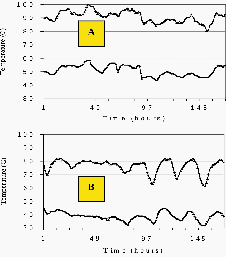
Figure 15 – Ambient temperature (bottom curve) and on B Phase Top FC (top curve) in the same cell without ventilation (A) and with forced ventilation (B)
6. Industry-specific application
The following aspects cover the role and significance of the switchgear in the operator’s network (industrial or public utility companies).
6.1 Switching duty and capacity
The choice and rating of the switchgear depends on the switching duty and the loads to be switched. Is the switchgear only required to switch normal currents? Or does it need to interrupt short-circuits too? Due to the transient switching operations, certain loads require overvoltage protection.
In other cases, additional rating criteria apply to the switch and switchgear.
Assigned configuration criteria for switchgear:
- Switchgear: circuit-breaker, switch or contactor with HRC fuses
- Rated electrical values
- Additional measures (e.g. overvoltage protection)
- Classes for mechanical and electrical endurance
- Design: circuit-breaker or switch-disconnector unit
Further Study – MV/HV switchgear (circuit breaker) switching capability and suitability for specific applications
MV/HV switchgear (circuit breaker) switching capability and suitability for specific applications
6.2 Switching frequency of the loads
Alongside the electrical requirements regarding the switching capacity, the switching frequency is an important selection criterion. The switching frequency depends on the process in which the switching device is used. Switches are rated for a short electrical lifetime (number of make-break operations), while contactors are rated for extremely long lifetimes; circuit-breakers fall in between.
Once a basic decision has been reached regarding the type of switchgear, standardized lifetime increments can be selected for the switches (endurance classes).
Assigned configuration criteria for switchgear:
- Switching devices: circuit-breaker, switch or contactor
- Classes for mechanical and electrical endurance
- Design of the switchgear assembly
- Air or gas-insulated system
- Withdrawable or fixed disconnector
- Loss of service continuity category
6.3 Frequency of switchover between busbars
In switchgear with double busbars, the lifetime of the disconnector plays a crucial role. For operational reasons, some networks require frequent switchovers between busbars. Due to the short mechanical lifetime of a disconnector / withdrawable unit as compared with a circuit-breaker, “standard” double busbar switchgear systems with just one circuit-breaker are unsuitable for this type of operation.
Standard double busbar systems have a common connection (cross connection between the two busbars) between the two disconnectors and the circuit-breaker.
Assigned configuration criteria for switchgear:
- Design of the switchgear
- Double busbar with common connection or two single busbars
- Interlocks and switchgear interlocking
Watch Video – Bus Section Interlocking
6.4 Availability (faults, redundancy, switchover time)
The term “availability” in this context means providing ways of compensating for line failures, for example, by means of redundant supply channels or defined switchover times. It also refers to the reliability of switchgear and features for planned maintenance activities or troubleshooting.
The switchgear provides the current paths for multiple supply channels and the switchover options. This can be used to determine the system circuit: single or double busbars and separated into different sections. The various options for linking busbars (busbar sections) with separate infeeds and the operating principle (NO / NC) of the couplings govern the rated current values.
Assigned configuration criteria for switchgear:
- Circuit arrangement:
- Single/double busbar
- Bus section panel
- Interlocks and switchgear interlocking
- Rated values of the switchgear:
- Normal current of the busbar(s)
- Peak current and short-time current
- Design: air or gas-insulated switchgear
- Loss of service continuity category:
- Design of partitions
Figure 16 – Example for the service continuity (LSC) of medium voltage switchgear
6.5 Switchgear modifications or extensions
Switchgear is sometimes set up in sub-sections or needs to be extended or modified during the course of its operating life. If such measures are anticipated, these should be taken into account in the planning stage.
Assigned configuration criteria for switchgear:
- Design
- Extension to include additional switchgear panels
- Rated values for normal and short-circuit current
- Replacement of instrument transformers
- Option of upgrading the secondary system
Further Study – Substation design choices and reasons for a new modern vs retrofit and upgrade an old one
Substation design choices and reasons for a new modern vs retrofit and upgrade an old one
7. Operating procedures
Operating procedure is a catch-all term that, with respect to configuration activities, will only be used to describe the following activities:
- Operation
- Work activities
- Maintenance
7.1 Operational activities
Operational activities include monitoring, switching, making settings, and reading displays / indicators. Operators can define how these activities are to be carried out, that is, whether they are to be carried out on site or remotely, (completely or partially) manually or automatically.
The automated integration of the switchgear in the network system management and production process makes important demands on the measurement, control, and remote control systems (secondary technology).
Assigned configuration criteria for switchgear:
- Design of the switchgear
- Air or gas-insulated system
- Withdrawable or fixed disconnector
- Type of compartments (access control)
- Loss of service continuity category
- Control and secondary equipment
- Interlocks and switchgear interlocking
- Manual or automatic drive mechanisms
- IP degree of protection
- Internal arc fault classification
Suggested Course – Learn How to Operate and Analyze Interlocking Schemes for Substation & Gas Insulated Switchgear (GIS)
7.2 Work (maintenance) activities
Activities in this context refers, for example, to modification, servicing, and maintenance activities or replacing fuses. When such activities are carried out, the system must be either fully or partially taken out of service.
How much of the system is taken out of service depends on the ‘loss of service continuity category’, which must be defined by the operator along with the type of access control to the disconnected compartments.
Assigned configuration criteria for switchgear:
- Loss of service continuity category
- Type of compartments (access control)
- Partition class
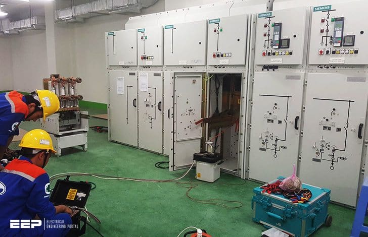
Figure 17 – Maintenance and testing Of medium voltage switchgear
7.3 Inspection and maintenance
System inspection and maintenance requirements can vary enormously and are subject to numerous influencing factors completely unrelated to electrical engineering, such as:
- Environmental conditions
- Industry-specific operating procedure
- Legal regulations
- Internal organization and work instructions
- Level of personnel training
Inspection and maintenance must be treated as separate activities. It may be the case that certain procedures require more frequent inspections, for example, which means that the switchgear must be more readily accessible. In this case, therefore, a completely hermetically-sealed system may not be the best solution because it cannot be accessed.
Assigned configuration criteria for switchgear:
- Design of the switchgear
- Air or gas-insulated system
- Withdrawable or fixed disconnector
- Loss of service continuity category
- Type of compartments (access control)
- Selection of switching devices and its endurance classes
Further Study – Prepare yourself for successful inspection and testing of MV metal-clad switchgear
Prepare yourself for successful inspection and testing of MV metal-clad switchgear
8. BONUS (PDF): Protection Study for 132kV, 33kV and 11/6.6kV Primary Substations
Download: Protection Study for 132kV, 33kV and 11/6.6kV Primary Substations (for premium members only):
References:
- Electrical Calculations and Guidelines for Generating Stations and Industrial Plants by T.E.Baker
Related electrical guides & articles


Edvard Csanyi
Hi, I'm an electrical engineer, programmer and founder of EEP - Electrical Engineering Portal. I worked twelve years at Schneider Electric in the position of technical support for low- and medium-voltage projects and the design of busbar trunking systems.I'm highly specialized in the design of LV/MV switchgear and low-voltage, high-power busbar trunking (<6300A) in substations, commercial buildings and industry facilities. I'm also a professional in AutoCAD programming.
Profile: Edvard Csanyi

Hi Edvard,
Really thinking to be meaningfully kind of contact with you referring in particular to your experience, I would ask firstly about any professional software If any suggestion from your side which/how to get it/them.
Like you some tears ago I have been, but in another form-cooperation with Schnedier Electric as pannel builder, which means we can cross some common moments in our professional life.
Regards, Altin