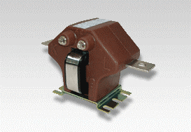
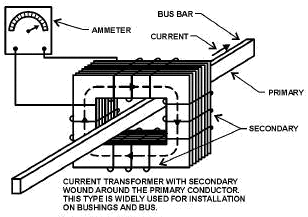
The primary of a current transformer typically has only one turn. This is not really a turn or wrap around the core but just a conductor or bus going through the “window.” The primary never has more than a very few turns, while the secondary may have a great many turns, depending upon how much the current must be stepped down. In most cases, the primary of a current transformer is a single wire or busbar,and the secondary is wound on a laminated magnetic core, placed around the conductor in which the current needs to be measured, as illustrated in figure 1.
If primary current exists and the secondary circuit of a CT is closed, the winding builds and maintains a counter or back EMF to the primary magnetizing force.
Should the secondary be opened with current in the primary, the counter EMF is removed; and the primary magnetizing force builds up an extremely high voltage in the secondary, which is dangerous to personnel and can destroy the current transformer.
For this reason, the secondary of a current transformer should always be shorted before removing a relay from its case or removing any other device that the CT operates. This protects the CT from overvoltage.
Current transformers are used with ammeters, wattmeters, powerfactor meters, watt-hour meters, compensators, protective and regulating relays, and trip coils of circuit breakers. One CT can be used to operate several instruments, provided the combined loads of the instruments do not exceed that for which the CT is rated.
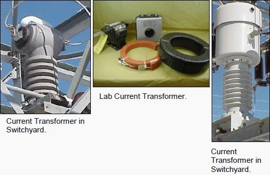
Secondary windings are usually rated at 5 amperes. A variety of current transformers are shown in figure 2. Many times, CTs have several taps on the secondary winding to adjust the range of current possible to measure on the primary.





It’s possible for a two primary cable to pass one ct check meter coil mean tow cable in per one ct coil
Hi dear Edvard
How can I recognize CT from CVT visually in substation?
Except wire thickness.
How can I recognize parallel and series connection?
We have thee generators operating parallel. Because of the space limitation on the load bus, we are connecting separate energy meters on individual generators. Now the question is, can we pass the secondaries of individual CTs pass through a single CT per phase to be connected to a single energy meter in order to get the sum of the total energy?
I have completed my bachelor degree in electrical engineering.i need a job in core side.please support and encourage me.
Thanks to all
Very good.
Hi,
I have contacted C T to Ammeter of Range 50A,CT Ratio is also as per mentioned on ammeter ie.50/5.I have passed loading wires(2nos)of one phase through C T. similarly I have contacted to other two phases.but none of the ammeters are showing the reading except slight deflection in 2 meters.what may be the problem. I have passed the loading wires in U shape instead of straight way.is it a problem.
It is very urgent.
Hi,
do you have any information about ct´s with doble winding? same secondary, different secondary?
A CT unit may have multiple secondary outputs depending upon load requirements
hi, i have connected current transformers to the 3 phase kilowatt hour meter as per manufacturers brochure. ie. 3 wires , one from s1 to kwh meter , one wire from s2 to kwh, and third wire live phase wire to the central pin of the kwh meter . This is repeated for the other 2 phases. the s2 connections are grounded together. problem is the meter will not turn. Do current transformers have polarities ie. in and out sides ? nothing is indicated on the ct. What could the problem be ??
Have u inserted the ct p1 side to source and p2 side to load?
yeah there is also polarity for current transformer i think in your case you are connecting p1 to the load side and p2 to the source side which is technically wrong because some C.Ts work this way some are not so kindly check these connections these should be proper.
excellent
Does a CT work properly on a MIMS cable? My thoughts are that the copper sheath would act like a faraday cage…. Has anyone had any experience with this?
excellent knowledge
Good Morning
I’m thinking to connect a Kwh meter in order to calculate the energy consumption but it is very difficult to connect the current transformer to the bars directly as most probably needed to be used split type as it is very difficult to dismantle the bars so I’m thinking to connect at three phases of mentioned generator smaller split type current transformers but at the cables connected with the 3 bars for transfering the power of the generator to the consumers.
My problem is that each phase bar splitted in three cable so i have nine cables to the output to the consumers and I don’t know if each one needed Current transformer.
In that case needed to be installed 9 transformers but I’m not sure for that.
Your assistance will be very usefull for my problem