
Estimated Study Time: 14 minutes
Number of Earthing Electrodes
Earthing Resistance and the number of earthing electrodes are both dependent on the resistivity of the soil as well as the amount of time it takes for fault current to pass through (one second or three seconds). The number of earth pits that are necessary can be calculated by dividing the whole area that needs to be earthed by the total area of one earth plate.
There is no general rule to calculate the exact number of earth pits and size of earthing strip, but discharging of leakage current is certainly dependent on the cross section area of the material so for any equipment the earth strip size is calculated on the current to be carried by that strip. First the leakage current to be carried is calculated and then size of the strip is determined.
For most of the electrical equipment like transformer, diesel generator set etc., the general concept is to have 4 number of earth pits. 2 no’s for body earthing with 2 separate strips with the pits shorted and 2 nos for Neutral with 2 separate strips with the pits shorted.
However a strip with lesser size which can carry a current of 35A can be used for body earthing. The reason for using 2 earth pits for each body and neutral and then shorting them is to serve as back up. If one strip gets corroded and cuts the continuity is broken and the other leakage current flows through the other run thery by completing the circuit.
Similarly for panels the no of pits should be 2 nos. The size can be decided on the main incomer circuit breaker.
For example if main incomer to breaker is 400A, then body earthing for panel can have a strip size of 25×6 mm which can easily carry 100A.
Number of earth pits is decided by considering the total fault current to be dissipated to the ground in case of fault and the current that can be dissipated by each earth pit. Normally the density of current for GI strip can be roughly 200 amps per square cam. Based on the length and dia of the pipe used the number of earthing pits can be finalized.
1. Measurement of Soil Resistivity
Accurate assessment of resistivity is crucial, as the electrode resistance is directly related to soil resistivity. Utilizing an erroneous soil resistivity value during the design phase may result in the measured impedance of the earthing system deviating considerably from the intended specifications. This may consequently result in significant financial repercussions.
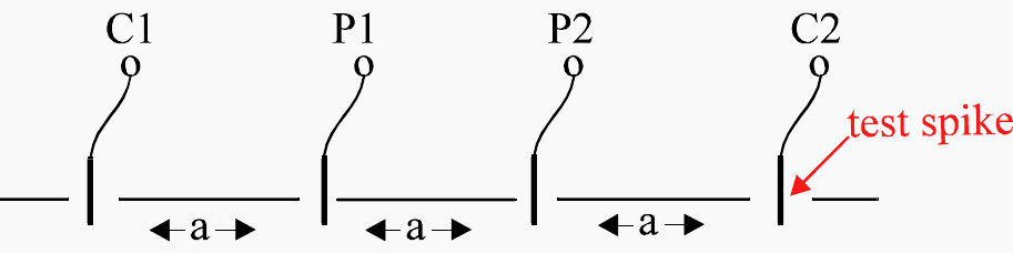
The testing process is generally conducted with a four-terminal earth tester. Four spikes are embedded in the ground, as illustrated in the diagram, separated by a distance of “a” meters. The penetration depth of each spike should not surpass “a” divided by 20 and typically does not exceed 0.3 meters.
The outside two spikes must be linked to the current terminals C1 and C2 of the instrument, while the inner spikes should be connected to the potential terminals P1 and P2.
Figure 1 – Four-terminal earth testing arrangement
It is crucial to verify that the test spikes are not positioned in alignment with subterranean metal pipelines or cables, as they will cause measurement inaccuracies.
The apparent resistivity is expressed by the formula: ρ = R × (2πa), where “R” is the instrument resistance in Ohms and “a” represents the spacing in meters.
The term “apparent resistivity” is utilized since the aforementioned formula presumes that the soil is homogeneous to a depth of “a” meters under the central point of the measurement traverse. We can acquire data regarding the real soil stratification by conducting a series of measurements, increasing “a” in increments of 1 m up to a separation of 6 m, followed by increments of 6 m up to a typical separation of 30 m. For extensive sites, particularly those with underlying rock, measurements may be recommended at separations of 50 m, 80 m, and even 100 m.
The testing apparatus employed must possess adequate precision to measure minimal resistance values at these considerable distances, namely ranging from 0.01Ω to 0.002Ω. Measurements should ideally be conducted in a region of relatively undisturbed soil.
Generally, smaller values of “a” result in increased soil resistivity due to significant effect from the surface soil, which typically loses moisture through drying caused by sunlight and wind. As the distance “a” grows, the apparent resistivity often diminishes, unless there is bedrock present beneath.
Consider the following scenario: you’ve chosen to put ground rods into your system that are three meters in length. We planned to use a three-meter-diameter separation between the test electrodes to determine the soil resistivity at a depth of three meters.
The soil resistivity can be determined by starting the Fluke 1625 and reading the resistance value in ohms. Here, we’ll pretend the resistance is 100 ohms. Hence, we are aware in this instance:
A = 3 meters, and
R = 100 ohms
Because of this, the soil resistivity would be:
r = 2 × PI × A × R
r = 2 × 3.1416 × 3 meters × 100 ohms
r = 1885 Ωm
2. Calculate numbers of pipe earthing
2.1 Earthing resistance and number of rods for isolated earth pit
Without buried earthing strip
The earth resistance of single rod or pipe electrode is calculated as per BS 7430:
R = ρ/2 × 3.14 × L (loge (8 × L/d) – 1)
Where:
- ρ = Resistivity of soil (Ω meter),
- L = Length of electrode (meter),
- D = Diameter of electrode (meter)
Example: Calculate isolated earthing rod resistance
Calculate isolated earthing rod resistance. The earthing rod is 4 meter long and having 12.2 mm diameter, soil resistivity 500 Ω meter.
R = 500 / (2 × 3.14 × 4) × (Loge (8 × 4/0.0125) – 1) =156.19 Ω.
The earth resistance of single rod or pipe electrode is calculated as per IS 3040:
R = 100 × ρ/2 × 3.14 × L (loge(4 × L/d))
Where:
- ρ = Resistivity of soil (Ω meter),
- L = Length of electrode (cm),
- D = Diameter of electrode (cm)
Example: Calculate number of CI earthing pipe
Calculate number of CI earthing pipe of 100mm diameter, 3 meter length. System has fault current 50KA for 1 sec and soil resistivity is 72.44 Ω-Meters.
Current Density At The Surface of Earth Electrode (As per IS 3043):
- Max. allowable current density I = 7.57 × 1000 / (√ρ × t) [A/m2]
Max. allowable current density I = 7.57 × 1000 / (√72.44 × 1) = 889.419 A/m2 - Surface area of one 100mm dia. 3 meter Pipe = 2 × 3.14 × r × L = 2 × 3.14 × 0.05 × 3 = 0.942 m2
- Max. current dissipated by one Earthing Pipe = Current Density × Surface area of electrode
Max. current dissipated by one earthing pipe = 889.419 × 0.942 = 837.83 A say 838 Amps - Number of earthing pipe required = Fault Current / Max.current dissipated by one earthing pipe
Number of earthing pipe required = 50000 / 838 = 59.66. We can round 60 No’s.
Total number of earthing pipe required = 60 No’s. - Resistance of earthing pipe (isolated) R = 100 × ρ/2 × 3.14 × L × (loge (4×L/d))
Resistance of earthing pipe (isolated) R = 100 × 72.44 / 2 × 3.14 × 300 × (loge (4×300/10)) = 7.99 Ω/Pipe - Overall resistance of 60 no of earthing pipe = 7.99/60 = 0.133 Ω.
Suggested Reading – Electrical thumb rules for switching, isolating and earthing
Electrical thumb rules for switching, isolating and earthing
2.2 Earthing resistance and number of rods for isolated earth pit
With buried earthing strip
Resistance of earth strip (R) As per IS 3043:
R = ρ / 2×3.14 × L × (loge (2×L×L/wt))
Example:
Calculate GI strip having width of 12mm , length of 2200m buried in ground at depth of 200mm, soil resistivity is 72.44 Ω-meter.
Resistance of earth strip (Re) = 72.44 / 2×3.14 × 2200 × (loge (2×2200×2200 / 0.2×0.012)) = 0.050 Ω
From above calculation overall resistance of 60 no of earthing pipes (Rp) = 0.133 Ω. And it connected to bury earthing strip.
Here net earthing resistance = (Rp×Re) / (Rp+Re) = (0.133×0.05) / (0.133+0.05) = 0.036 Ω
2.3 Total earthing resistance and number of electrode for group
Parallel electrodes
In cases where a single electrode is not sufficient to provide the desired earth resistance, more than one electrode shall be used. The separation of the electrodes shall be about 4 m. The combined resistance of parallel electrodes is a complex function of several factors, such as the number and configuration of electrode the array.
The total resistance of group of electrodes in different configurations as per BS 7430:
Ra = R (1 + λa/n), where a = ρ / 2 × 3.14 × R × S
Where:
- S = Distance between adjustment rod (meter),
- λ = Factor given in table below,
- n = Number of electrodes,
- ρ = Resistivity of soil (Ω meter),
- R = Resistance of single rod in isolation (Ω)
| Factors for parallel electrodes in line (BS 7430) | |
| Number of electrodes (n) | Factor (λ) |
| 2 | 1.0 |
| 3 | 1.66 |
| 4 | 2.15 |
| 5 | 2.54 |
| 6 | 2.87 |
| 7 | 3.15 |
8 | 3.39 |
| 9 | 3.61 |
| 10 | 3.8 |
For electrodes equally spaced around a hollow square, e.g. around the perimeter of a building, the equations given above are used with a value of λ taken from following table.
For three rods placed in an equilateral triangle, or in an L formation, a value of λ = 1.66 may be assumed.
| Factors for electrodes in a hollow square (BS 7430) | |
| Number of electrodes (n) | Factor (λ) |
| 2 | 2.71 |
| 3 | 4.51 |
| 4 | 5.48 |
| 5 | 6.13 |
| 6 | 6.63 |
| 7 | 7.03 |
| 8 | 7.36 |
| 9 | 7.65 |
| 10 | 7.9 |
| 12 | 8.3 |
| 14 | 8.6 |
| 16 | 8.9 |
| 18 | 9.2 |
| 20 | 9.4 |
For Hollow square total number of electrodes (N) = (4n-1).
The rule of thumb is that rods in parallel should be spaced at least twice their length to utilize the full benefit of the additional rods. If the separation of the electrodes is much larger than their lengths and only a few electrodes are in parallel, then the resultant earth resistance can be calculated using the ordinary equation for resistances in parallel.
Typically, a 4 spike array may provide an improvement 2.5 to 3 times. An 8 spike array will typically give an improvement of maybe 5 to 6 times.
The Resistance of Original Earthing Rod will be lowered by Total of 40% for Second Rod, 60% for third Rod,66% for forth rod.
Example: Calculate total earthing rod resistance of 200 parallel electrodes
Calculate Total Earthing Rod Resistance of 200 Number arranges in Parallel having 4 Meter Space of each and if it connects in Hollow Square arrangement. The Earthing Rod is 4 Meter Long and having 12.2mm Diameter, Soil Resistivity 500 Ω.
First Calculate Single Earthing Rod Resistance:
- R = 500/ (2 × 3.14 × 4) × (Loge (8 × 4 / 0.0125) − 1) = 136.23 Ω.
Now calculate total resistance of earthing rod of 200 number in parallel condition:
- a = 500 / (2 × 3.14 × 136 × 4) = 0.146
- Ra (Parallel in Line) = 136.23 × (1+10 × 0.146 / 200) = 1.67 Ω.
If earthing rod is connected in Hollow square than rod in each side of square is 200 = (4n-1), so n = 49 No.
Ra (in hollow square) = 136.23 × (1 + 9.4×0.146 / 200) = 1.61 Ω.
Suggestd Video Course
Suggested course – ETAP Power System Design and Analysis Course: Learn To Resolve Power System Issues
ETAP Power System Design and Analysis Course: Learn To Resolve Power System Issues
Related electrical guides & articles


Jignesh Parmar
Electrical Middle management professional having more than 22 years rich and dynamic experience in Project Execution / Project Management / Designing / Maintenance diversifies from Electrical Power Transmission (400KV/220KV/66KV)- Distribution(11KV/220V) to Lifts-HVAC-Ventilation-Fire Fighting-Fire Alarm-Lifts-CCTV-Stack Parking Works (High Rise Buildings, Townships, Shopping Complex, Commercial Complex, School, Temple).Profile: Jignesh Parmar

In “Resistance of earthing pipe (isolated) – as per IS3043, considering natural log, answer should be 18.4 ohm, not 7.99 ohm
Right, also
EXAMPLE -1 Calculate Number of Pipe Earthing
R = ρ / 2 x 3.14 x L (Loge (8 x L / d) -1)
ρ Resistivity of soil (Ω meter), 500 Ω-meter
L Length of electrode (meter), 4 meter
D Diameter of electrode (meter) 12.2 mm
“Calculate isolated earthing rod resistance. The earthing rod is 4 meter long and having 12.2mm diameter, soil resistivity 500 Ω meter.
R=500/ (2×3.14×4) x (Loge (8×4/0.0125)-1) ”
R 136.3010059
19.9044586 7.847762537 1 6.847762537
A B
Answer is 136.3010059 Ohms not 156 Ohms!
How to Calculate feeder to feeder, Down Stream Fault Level from
(transformer to Main Panel to Sub Panel to MSB DB to Light Switch Board)
Hello,
Any reply on the issue of lambda=10?
Can’t understand either.
Please let me know how to calculate the withstand capacity of a group of earthing?
Dear Sir,
Shall we know why chemical earthing is better than plate earthing and what are its IS, IES standards.
Regards,
Vinod Kinekar
Surface area of one 100mm dia. 3 meter pipe= 2×3.14 x r x L
Please how did you get valve of r to be 0.05?
Pls advise how you got Lambda λ equals to 10 from the equation of the Ra:
Ra (Parallel in Line) =136.23 x (1+10×0.146/200) = 1.67 Ω.
Now calculate total resistance of earthing rod of 200 number in parallel condition:
a = 500/(2×3.14x136x4) =0.146
Ra (Parallel in Line) =136.23x (1+10×0.146/200) = 1.67 Ω.
I want to knowledge of electrical fields about their electrical equipment.. Etc
Please i have the following parameters after my due calculations carried out,
Size of Generator——————–250Kva
Panel Rating ———————–350A
Cable size—————————–240sqMM
Earthing Cable (guess)————120sqMM(Half)
please sir i was now asked to calculate the following:
Do the earthing electrode resistance design as per BS 7430 or IS- 3040/43 to meet the reuse R¬< 1.0U.
a. Determine the earth rod diameter/length
b. The total number of earth rod to be used.
Thanks for the lecture. At least I have gotten something from it. How do I calculate the fault current in 1*15MVA, 33/11kv substation
V secondary = 11kV
%Z = ___?
I secondary= ((150×1000)/(Sqrt of 3*11000))
=_____ kA
Isc =(I secondary / %Z)
=____kA
The you for your generousity
Sir,
Is the number of earth pits get reduced if I use copper clad steel (250 micron) instead of GI for vertical electrode.
would u please tell me sir that how could have select the transformer neutral pit and strips
There are a lot of mistakes in either the given Formulas or the calculations. So please, get them corrected.
I think it is improper to calculate the size of earthing strip on the basis of rating of main incomer.The short ckt rating of the system should be taken into consideration.The earthing strip should be able to carry fault current for 1 sec.
GOOD SUBJECT
We are leading manufacturer and suppliers of high quality chemical earthing electrode manufacture,copper bonded electrode manufacture,pure copper earthing electode manufacture,gi chemical electrode manufacture and chemical earthing Compounds meeting industry standards for residential, commercial and industrial sectors.We specialize in installation and testing highly conductive, corrosion free Earthing system as well as lightning protection system. Our services extend to private businesses (large and small) as well as Government agencies ranging from Domestic, state to national levels.
Hi Sir
Our Company is construction company, and we construct building by latest Technic by using puff i.e metallic wall, so please tell me how much earth pit required as per area.
Dear Sir
why same unit is not used for length and diameter in below formula?
please reply
R = 100×72.44 /2×3.14x300x(loge (4X300/10))
R = 100×72.44 /2×3.14x300x(loge (4X300/10)) can’t find the same answer as yours. How do you get the answer?
Dear Sir , In above problems , in formulae there is natural logarithm i.e. ln , what in calculation you are using log base 10 ???????
Sir i have a doubt regarding the earthing.
One of my work site, the earth resistance requirement is less than 3 ohm. The site is a low tension project. I don’t know how to calculate the number of earth pit for that site. Please tell me the equation to find out the no. of earth pit required. The power is available from electricity board transformer having 160 kVA. Please help me.
Dear Sir,
You wrote that for 100kVA transformer, 70A would be neutral current which means a strip of GI 25x3mm should be sufficient. But, as i know Strip should be sized as per neutral fault current because I is fualt current in strip sizing formula as per IS 3043.
Formula : S=I x root t / K
Kindly clear.
The Formula you have mentioned is for Short circuit current. I believe the size of the copper tape was selected based on its ‘Ampacity’ (Capacity to carry current). This information can be found in the catalog.
Hi. Very useful info, thank you. I think there may be an error in how you interpreted the loge formula for the calculation of electrode resistance. Your calculations work out if you use log10 but not natural log (log e). Please re-check
Dear Mr. Raj,
Pls advise how you got Lambda λ equals to 10 from the equation of the Ra:
Ra (Parallel in Line) =136.23 x (1+10×0.146/200) = 1.67 Ω.
BR
Dear Sir,
Usefull information every time getting from your articles.
I need information on Cu. bonded earth electrode and GI earth electrode fault current carrying capacity.
We are facing issues of GI earth electrode corrosion so we need to change with Cu. bonded earth electrode with carbon base back fill compound.
Nowadays chemical type Earth Electrodes are popular.
I want to design an Earthing system based on chemical type Earth Electrodes, for which no standard is available..
Can I get guidance for the design?
DILIPKUMAR D DESAI
Dear Sir,
Thanks for your question.
Chemical Maintenance free earthing is based on the IEC standrad 62561-1,2 & 6. The seletion of earth electrode is as per the standrad current rating as well as fault current. May I know for what rating of equipment you are going to use. regards
Amit Kumar
hello, please tell me how did you get the lamda factor 10 for 200 electrodes in the last example. The table has no.s up to 20 electrode for hollow square shape. thanks
V Nice work done !! congratulations to share the knowledge. Quick note the values I got for the calc is 136 not 156.
Thanks
HI…I can’t get a hang of it on how I input the “Loge ((8×4/0.0125)-1)” formula so I tried to use e as the base of log…my first thought that my calculation is a mistake so i tried to the internet and I still can’t get the result of 136.23 Ω….pls help me…i would be grateful …thank you
please if the above equation depend on the total area or because some different equation depend on surface area
Dear Jignesh,
I had some doubt regarding earthing of generators and assosiated service pillar.
I have 3 x1000kVa generator and soil resistivity of 27 Ohm-M. I had done a calculation and found out 19 pits required and each pit of 20mtr long electrode of dia 17.2mm.
I just want to confirm whether my calculation is right or wrong.
I look forward for your reply
Thanks
Is it right for a domestic building to bond the main earthing of the building to the earthing for the lightning arestor ?
Sir,
I just to know if touch and step voltage is still applicable on areas like piperacks? Are we only going to compute the required earth rods in this areas (piperack)?
Dear Sir’s, Can any one help with the details of – How many Equipment Earthing/ Body Earthing can be connected or allowed to one single earth pit.
Just be careful with the calculation and design of your electrode systems. One of the biggest issues with multiple earthing points at any equipment is the potential to have circulating currents. I found the best way to design an suitable electrode system is to produce a spreed sheet with all the different methods and play with the input data until you have a working solution that can realistically constructed.
R=500/ (2×3.14×4) x (Loge (8×4/0.0125)-1) =156.19 Ω
The result Wrong , it must be 136.315
Thanks
But the most important thing I think is to determine the soil resistivity. Because this varies and depends on the nature of the soil.
Can you help us with our earthing requirement. We have setup a new test room with some panels, HV test set etc. We require earthing for these and need to achieve less than 1 ohm. We have thought about making 4 pits for earthing. But we are not completely sure how to proceed. Can you give us an overview on how to proceed.
Dear Sir,
I am electrical Designer past 9 years.
as per past experience i did the design the following
1) for Example 500 kVA Trans former & 500 kVA DG set installed in one of the project
I given 2 No Body Earthing GI plate for Transformer &2 Nos NE eathing CU for Transformer
& DG also same like 2 BE & 2 NE
I want to know How to calculate the
No of the Eath pit calculation
Kindly send to us my mail id
it useful for me
Regards
L.Prakash
Yes I am an electrical engineer with over 37 years experience in Transmission & Distribution system & Thermal Power Plant Electrical systems in Design & Engineering field.
1.For EHV substations we design Earthing systems as per IEEE80 considering Soil resistivity, system fault current,duration then Conductor sizing, step, touch and mesh voltage and finally Total grid resistance etc.
2.My present requirement is for a Wind Electric Generator Unit Substation (a Collector Substation at 33kV level) i.e. below the respective WEG, comprising a step up Transformer to 33kV, VCB, CT, PT, ISOLATOR and LA etc mounted on steel structures over concrete foundation. Nothing but a mini size WEG Unit Substation with a max. of 33kV system voltage. So, for this type of mini or small WEG unit SSs what type earthing system are recommended and please throw me some light on the same with full details such as calculation, recommendation and any document in support of the same.
Mob.9789836525
Hi, i am an EEE- engineer.
how i can download it.
best regards
Great article, just a couple of issues. In the opening picture the main earthing lead is shown with a spiral twist in it, this acts as an inductor on AC and may limit the earth fault current flowing during a fault. If this electrode is the main electrode of a ‘TT’ system, as defined in BS 7671, the top of the earth electrode must be covered by an insulating cover. This is to avoid any person or animal receiving a shock by touching the electrode during a fault. It would improve the safety and effectiveness of the eart electrode by allowing the top of the electrode to be below ground level. BS 7671 requires that a label should be fitted to the earthing lead at the connection to the electrode with the wording ‘Safety electrical earth, do not remove.
The theory is good but practial issues are not adequately adressed.
AT LAST MY PROBLEM WAS SLOVED BY THE THIS AUTHOR BUT THERE IS MISTAKE IN THE FORMULA IN PART -II FOR CALCULATION OF NO OF ELECTRODES. FORMULA SAYS SOME THING BUT EXAMPLE SAYS SOME VALUES PL CORRECT THE SAME.
Merci pour tous ce que vous présenter comme idées, mais la traduction de la langue anglaise à la langue française et en général déformée, car la zone dont nous dépendent est francophone, c’est pour cela que nous trouvons des difficultés pour récolter convenablement vos cours et vos conseils.
Salutations distinguées
NADJI Youcef