Low-resistance earth electrode and soil
A good, low-resistance earth electrode depends upon a low-resistivity soil in a spot where you can drive in your electrodes. There are two approaches to picking your location:

- Drive rods in various locations to such depths as may be required and test their resistances while they are being driven.
- Measure the earth resistivity before driving ground rods. Then calculate the number and length of rods required.
To get a low-resistance electrode in an unfavorable location, lay out straight lines 10 ft apart, covering the area. Drive four stakes 10 ft apart, but not more than 6 in. deep, along a line a-b-d-c, as shown in Figure 1 below.
Then, shift the stakes along the line in question to points b-c-d-e, c-d-e-f, and so on (see Figure 1) and test until the entire line has been covered. Next, move to the next line and repeat the process until the whole chosen area has been covered.


The location giving the lowest value for R has the lowest specific resistance for the soil to the chosen depth of 10 ft. The spot is likely to give you the best earth electrode. If you want results affected by the average earth resistivity to a depth of 20 ft, repeat the survey on lines 20 ft apart and with stakes spaced 20 ft apart. Such surveys do not require much time and can pay off in ensuring a good grounding system.
With ground resistance testers’ high resistance test circuits, testing can be performed on a paved surface.
Alternate Method
Another way is to drive rods or pipes in various locations to such depths as may prove practicable, testing their resistance while they are being driven. In this manner, you can usually tell at once when moisture or other good conducting earth is reached.
However, the work involved is apt to be much more than with the first method.
Seasonal Variations in Earth Resistivity
We know the effects of temperature, moisture, and salt content upon earth resistivity. It makes sense, therefore, that the resistivity of soil will vary considerably at different times of year. This is particularly true in locations where there are more extremes of temperature, rainfall, dry spells, and other seasonal variations.


From the preceding discussion, you can see that earth resistivity is a very variable quantity. If you want to know what the value is at a given location, at a given time of year, the only safe way is to measure it. When you use this value for survey work, the change in the value, caused by changes in the nature of the sub-soil, is the important thing; from the variations in resistivity you can obtain useful survey results.
Other main reason for measuring earth resistivity is to design earth electrode systems for electrical power systems, lightning arresters, and so on.
The measured resistivity values are used in standard engineering formulas that calculate factors like number and depth of rods necessary to achieve a required ground resistance, thus reducing the amount of trial and error in the installation of an effective ground.
Earth resistance varies directly with earth resistivity and it is helpful to know what factors affect resistivity.
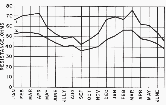
The curves of Figure 3 above illustrate several worthwhile points. They show the expected change in earth resistance (due to resistivity changes) over a 1-1/2 year period. They also show that the deeper electrode gives a more stable and lower value. We conclude that the moisture content and temperature of the soil become more stable at greater distances below the earth’s surface.
Therefore, the earth electrode should reach a deep enough level to provide //
- Permanent moisture content (relatively speaking).
- Constant temperature (below frost line; again, relatively speaking).
How earth resistivity is measured?
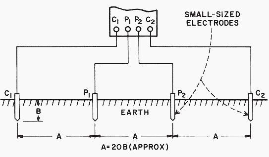
A four terminal instrument is used to measure earth resistivity. Now, however, you use four small-sized electrodes driven down to the same depth and equal distances apart in a straight line (Figure 4). Four separate lead wires connect the electrodes to the four terminals on the instrument, as shown. Hence, the name of this test: the four terminal method.


Dr. Frank Wenner of the U.S. Bureau of Standards (now NIST) developed the theory behind this test in 1915. He showed that, if the electrode depth B is kept small compared to the distance between the electrodes A (B=1/20A is generally recommended), the following formula applies:
ρ = 2πAR
where:
- ρ is the average soil resistivity to depth A in ohm-cm,
- π is the constant 3.1416,
- A is the distance between the electrodes in cm, and
- R is the earth tester reading in ohms
In other words, if the distance A between the electrodes is 4 ft, you obtain the average earth resistivity to a depth of 4 ft as follows:
- Convert the 4 ft to centimeters to obtain A in the formula:
4 · 12 · 2.54 cm = 122 cm - Multiply 2 πA to obtain a constant for a given test setup:
2 · 3.14 · 122 = 766
Now, for example, if your instrument reading is 60 Ω, the earth resistivity would be 60 x 766, or 45,960 ohm-cm.
Ground Resistance Measurement, Fall potential method
Ground Resistance Testing (VIDEO)
Reference // A Practical Guide To Earth Resistance Testing by Megger


It’s such a good in formation.