
Estimated Study Time: 36 minutes
Why surge protection?
Prevention is better than cure, we all know this, and this is true not only for people, but also for the health of your electrical and electronic components and equipment. Smart and cost-effective strategies demand an investment in surge protection. Such an investment would only be a fraction of the amount of possible damage! It’s always like this.
 How to handle overvoltages before any damage is done? Surge protection in a nutshell
The shut down of a manufacturing plant because of the failure of a PLC or the collapse of industrial data transmission can be very costly. But the significant overhead in repairing the problem is not the only factor. You must also take into account the system down times.
The lifespan of your components (mean time between failure) will also be shortened. Surge voltages present a significant danger and this can be demonstrated in many other ways than the examples given in damage statistics from property insurers.
All electrical equipment is potentially threatened by surge voltages: this includes free-standing high-voltage switching facilities and also electronic micro-components. For low voltages, this risk is predominant in the fields of power supply, measure and control technology, telecommunications, and data transmission.
Surge protection has become an area of increasing significance. On the one hand, electrical and electronic components continue to get smaller. On the other hand, the levels of automation in the industrial and consumer electronics sectors are continuing to rise.
The safety clearances for insulation decrease as do the tolerance limits. Electronic circuits function at low voltage levels of only several hundred volts. Thus surge voltages can present a significant danger.
- What are overvoltages?
- How do overvoltages occur?
- Lightning
- Conductive coupling
- Inductive coupling
- Capacitive coupling
- Radiation coupling
- Switching operations (transients)
- Electrostatic discharges (ESD)
- Faulty switching operations
- Interference voltages
- The forms of interference voltage
- Normal-mode (symmetrical) interference
- Transverse (normal-mode) voltage
- Common-mode (unsymmetrical) interference
- Longitudinal (common-mode) voltage
- What are the consequences?
- How do we achieve surge protection?
- Surge protection concept
- General installation advice
1. What are overvoltages?
Surges are extremely high voltages that damage or even completely destroy insulation and hence impair or completely disrupt the function of electrical and electronic components of all kinds.
Every electrical component is provided with insulation to isolate the electrical voltage from earth or other voltage carrying parts. The insulation strength is dependent on the rated voltage and the type of electrical component, as stipulated by the IEC regulations.
It is tested by applying the prescribed voltages for a defined period of time. If the test voltage is exceeded in operation, the safety effect of the insulation is no longer guaranteed, which is not good, and the component might be damaged or completely ruined. Surges are voltage pulses that are higher than the test voltage, and these could detrimentally affect an electrical component or system.
This means that components with a high rated voltage may be capable of withstanding a surge voltage. But components with a lower rated voltage would be very much at risk from the same surge.
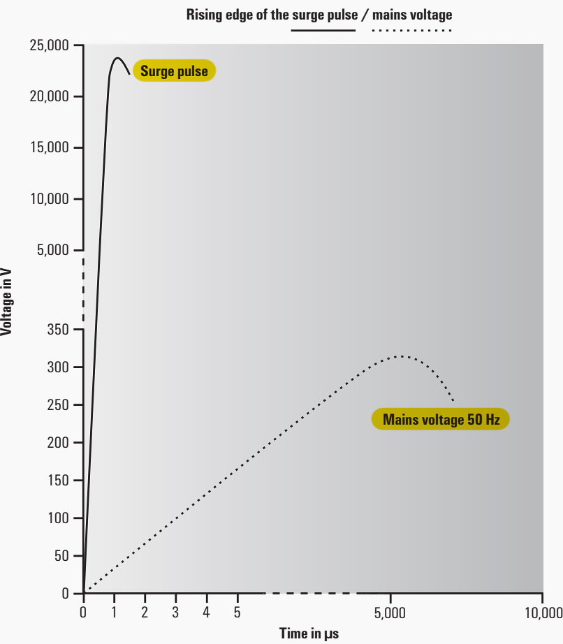
Individual surge pulses, which have a high frequency because of their physical formation, have a current rise that is about ten thousand times steeper compared with 50 Hz voltage. If the current rise time in the 50/60 Hz range is 5 ms, then for an overvoltage it is around 1 µs. These surges are designated as “transient” voltages.
This means that they are short-lived, temporary oscillations. Their shape and frequency depends on the impedance of the circuit.
Figure 1 – Edge behaviour between a 50 Hz sine wave and surge pulse
Go back to the Contents Table ↑
2. How do overvoltages occur?
Surges are primarily caused by transient switching operations, lightning due to atmospheric discharges, electrostatic discharges (ESD), and faulty switching operations.
2.1 Lightning
Bolts of lightning comprise extremely high currents. They can cause a large voltage drop and a large rise in potential, even in well-earthed buildings or systems, despite low earthing resistances. This can then result in a galvanic, inductive or capacitive coupling of surge voltages within the circuits of electrical or electronic facilities. Any insulation will also be penetrated.
So, in reality, there are no electrical isolation methods which provide reliable protection against surge voltages. Analogue converters, relays or opto modules are important for separating potentials, but they are definitely not surge protection components.
The various forms of coupling must be considered in order to understand the effects of lightning.
Figure 2 – The discharge curve of natural lightning (red) and a simulated lightning strike from lightning current generator (green)
Go back to the Contents Table ↑
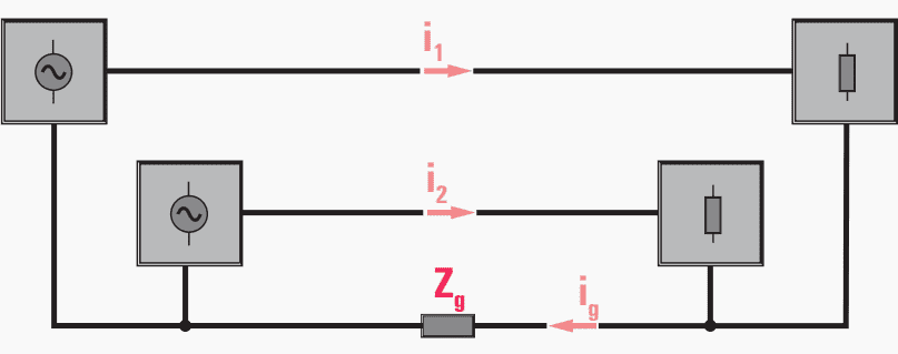
2.2 Conductive coupling
Surges are transferred directly into circuits via common earthing impedances. The magnitude of the overvoltage depends on the amperage of the lightning and the earthing conditions. The frequency and the wave behaviour are mainly determined by the inductance and the speed of the current rise.
Even distant lightning strikes can lead to overvoltages in the form of travelling waves, which affect different parts of electrical systems by way of conductive coupling.
Figure 3 – Conductive coupling
Go back to the Contents Table ↑
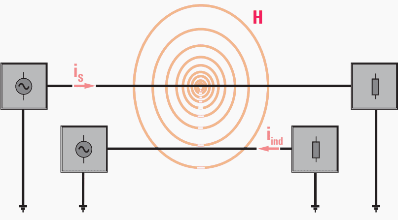
2.3 Inductive coupling
A high-amperage lightning strike generates a strong magnetic field. Starting from here, overvoltages reach nearby circuits by means of an induction effect (e.g. directly earthed conductor, power supply lines, data lines, etc.).
According to the transformer principle, the coupling of induced voltages is considerable owing to the high-frequency current di/dt – even when primary and secondary windings consist of only a single winding each, i.e. the inductance is low.
Figure 4 – Inductive coupling
Go back to the Contents Table ↑
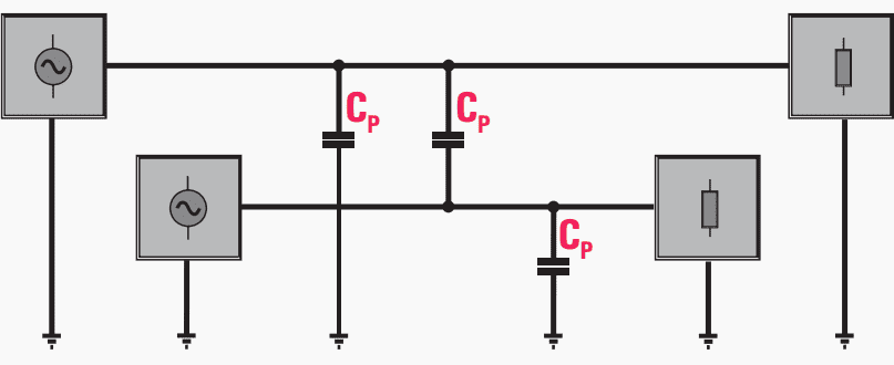
2.4 Capacitive coupling
A capacitive coupling of overvoltages is also possible. The high voltage of the lightning generates an electric field with a high field strength. The transport of electrons can cause a capacitive decay to circuits with lower potentials and raise the potential concerned to an overvoltage level.
Figure 5 – Capacitive coupling
Go back to the Contents Table ↑
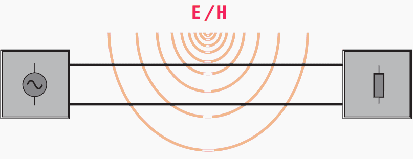
2.5 Radiation coupling
Electromagnetic wave fields (E/H field), that also ensue during lightning (distant field condition, E/H field vectors perpendicular to each other), affect conductor structures in such a way that coupled overvoltages must be expected even without direct lightning strikes.
Permanent wave fields from strong transmitters are also able to cause coupled interference voltages in lines and circuits.
Figure 6 – Radiation coupling
Go back to the Contents Table ↑
2.6 Switching operations – Transients
More often, it is switching operations that cause interference rather than lightning. High-amperage shutdowns in the mains in particular can generate considerable overvoltages (e.g. welding equipment).
Switching operations generate overvoltages because, due to their construction, switching contacts that switch the current on or off do not operate in synchronisation with the current zero of an alternating current. This means that in the majority of cases there is a very rapid change of current, from a high value to zero (di/dt).
The situation is similar in the case of short-circuits in the mains because these also represent a rapid switching operation.
Suggested course – Learn to Analyse Faults in Power Systems: Theoretical and Real-World Examples
Learn to Analyse Faults in Power Systems: Theoretical and Real-World Examples
Go back to the Contents Table ↑
2.7 Electrostatic discharges (ESD)
Electrostatic discharges (ESD) caused by frictional charges are well known. You can experience them when getting out of a car or walking across a carpet. These discharges can be over 10,000 volts in strength. We speak of ESD when these discharge to a lower potential. If such a charge strikes, for example, electronic components, then these can be completely ruined.
Special care is taken, for example, with ESD issues when manufacturing electronic circuit boards.
Go back to the Contents Table ↑
2.8 Faulty switching operations
Again and again, we experience faulty switching operations in the 50/60 Hz mains. These can be caused by a failed power supply unit controller or incorrect wiring in a panel. The relatively high voltages that can occur as a result also represent dangerous overvoltages.
Protection against these is vital.
Go back to the Contents Table ↑
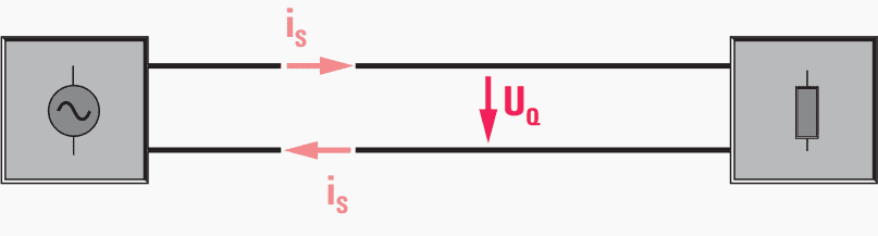
2.9 Interference voltages
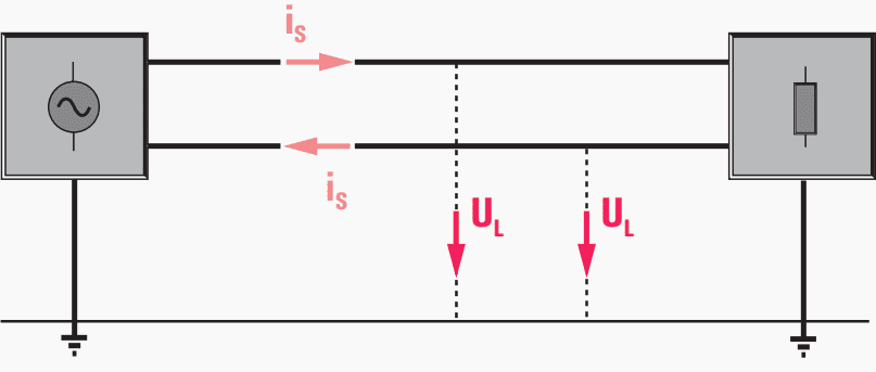
Surge voltages that occur between live conductors, or between a live conductor and the neutral conductor, are called transverse voltage or symmetric interference UQ.
Figure 7 – Transverse voltage or symmetric interference UQ
Surge voltages that occur between a live conductor and the PE conductor are called longitudinal voltage or asymmetric interference UL.
Figure 8 – Longitudinal voltage or asymmetric interference UL
Go back to the Contents Table ↑
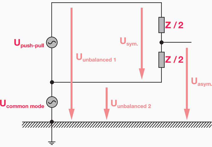
2.10 The forms of interference voltage
Coupled transient surge voltages are basically either symmetric (differential-mode interference) or asymmetric (common-mode) interferences, which are measured as longitudinal or transverse voltages.
Go back to the Contents Table ↑
2.11 Normal-mode (symmetrical) interference
A voltage between supply and return conductor, differential mode voltage/current. Occurs mainly at low interference frequencies in the existing lines. The interference current causes an interference voltage directly at the interference sink (between the input terminals). With galvanic or inductive coupling, both the effective sources and the interference sources are connected serially.
In unsymmetrical circuits (earthed one side), the normal-mode interference occurs as unsymmetrical voltages.
Suggested course – Symmetrical Components Technique for Power System Protection and Control Engineers
Symmetrical Components Technique for Power System Protection and Control Engineers
Go back to the Contents Table ↑
2.12 Transverse (normal-mode) voltage
This is a transient coupled interference between two active conductors. For asymmetric circuits with ground potential, the transverse voltage is equal to the longitudinal voltage. A remedy or limitation may be achieved by twisting the corresponding wires together and shielding or multiple shielding with cable sheath.
This reduces the induction of transverse voltages.
Go back to the Contents Table ↑
2.13 Common-mode (unsymmetrical) interference
Voltage between conductor and reference potential (earth), common-mode voltage/current. Mainly caused by a capacitive coupling (electrical field). Therefore, significant common-mode interference currents only flow at higher interference frequencies.
The interference voltage at the potentially susceptible device is caused by different voltage drops at the supply and return conductors (in each case between input terminal and reference earth).
The forward and return conductors have the same interference voltages compared to the reference ground. In unsymmetrical circuits, common-mode interference occurs as unsymmetrical voltages between the individual conductors and the reference earth.
Suggested Course – Power System Analysis Course: Load Flow and Short Circuits
Power System Analysis Course: The Essentials of Load Flow and Short Circuits
Go back to the Contents Table ↑
2.14 Longitudinal (common-mode) voltage
A coupled transient interference voltage between an active conductor and the earth potential. As a rule, the longitudinal voltage is higher than the transverse voltage (transverse voltage is lower owing to cable shielding and twisting).
Longitudinal voltages caused by lightning currents on cable shielding can assume quite high values, especially in the case of long lines entering a building from the outside.
Go back to the Contents Table ↑
2.15 What are the consequences?
The impedances and stray capacitances are equal in ideal circuits. This means that the currents in the supply and return conductors generated by coupled overvoltages are also equal and so do not generate any interference voltage.
However, in practice the impedances and stray capacitances in the supply and return conductors are different.
This results in unequal currents which cause different voltages to earth in the supply and return conductors. This means that the unequal impedances lead to the common-mode voltage becoming, for the most part, a normal-mode voltage because of the dissimilarity in the voltages to earth of the supply and return conductors.
Figure 9 – Different voltages to earth in the supply and return conductors
Go back to the Contents Table ↑
Figure
3. How do we achieve surge protection?
We have to consider surge protection from two points of view:
Point #1 – General protective measures during the planning and construction of buildings and electrical installations.
Point #2 – Special protective measures realized by the installation of additional surge protection components.
Go back to the Contents Table ↑
3.1 Planning buildings and electrical installations
Some primary measures to prevent or limit surge voltage damages can be incorporated into buildings and electrical/electronic facilities right from the start. Although such measures can achieve only basic protection, they can save some of the costs involved when it comes to planning an effective, complete protection concept.
Beginning with the first phase of construction, it is very important to set up an earthing or equipotential bonding facility of sufficient size. Only this will ensure full equipotential bonding in the event of a malfunction.
When planning the electrical installation, care must be taken to ensure that electrical systems with dissimilar rated voltages are kept separate. Corresponding protection zones can then be set up and this leads to cost-savings in the surge protection.
Furthermore, the physical separation or shielding of lines that can influence each other is a good way to achieve maximum electrical isolation. Another good option is to split up the individual phases of three-phase systems corresponding to their functions, e.g. one phase only for the supply to instrumentation and control systems.
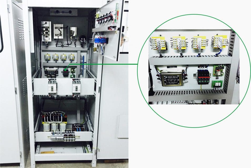
Of course, all these primary measures do not achieve complete protection. To do this, you must install additional protective components.
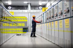
Figure 10 – Surge protection SP320/4P installed in the 22KV power substation battery charging panel
Go back to the Contents Table ↑
3.2 Surge protection components
Surge voltages are kept away from at-risk electrical components by first reducing them to a harmless dimension before they reach the components.
The quick reaction times of surge arresters are used to provide this protection. They must respond during the high-frequency rising phase of the overvoltage, i.e. before a dangerous value has been reached, and quench the overvoltage.
The response time lies in the nanoseconds range.
In addition, it is absolutely essential that the surge protection component is very quickly available again in electrical terms after the surge has been quenched by earthing it. This is necessary to ensure that the function of the circuit is guaranteed.
Good surge protection is characterized by:
- Fast response behaviour
- High current-carrying capacity
- Low residual voltage
- Good reactivation time
There are many manufacturers that can supply protective components that fulfil these criteria. Depending on the application, these usually consist of a combination of individual components.
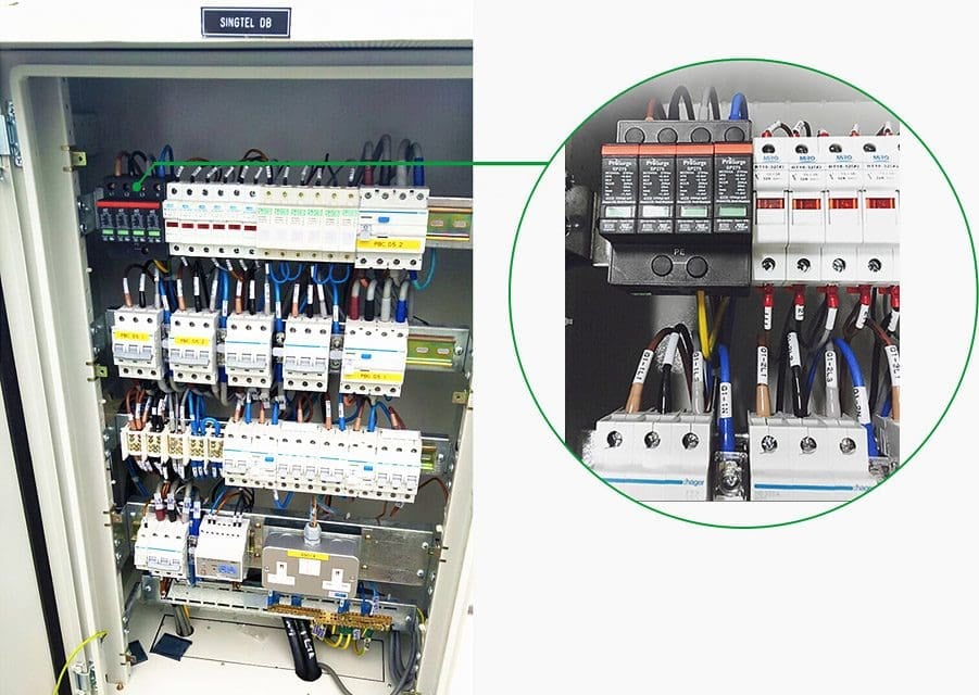
The first protection mechanism is always installed at the building entrance, so that the initial coupling interference can be directly “intercepted” before the sensitive end devices.
Figure 11 – Surge protection device installed in electrical panel
Go back to the Contents Table ↑
4. Surge protection concept
4.1 Fundamental concept of protection
One important aspect of surge protection is the area of power supply and distribution. The procedure is linked to the systematic subdivision prescribed by the protective zones concept and the corresponding coordination of surge arresters. Protection of power supply lines forms the basis for protecting all electrical and electronic equipment right down to the smallest and most sensitive components.
A fundamental requirement for effective surge protection is the presence of properly functioning equipotential bonding to IEC 60099-5 in a series, or better still, star or grid arrangement.
IEC 60071-1 (insulation coordination) divides overvoltage protection for power supplies and power distribution into the following three areas:
4.1.1 Power supply
The surge voltage strength of the insulation is 6 kV from the incoming supply to the building – by means of underground cables or overhead lines – right up to the main distribution board (backup fuse and meter cupboard). Owing to the lightning protection zoning concept and the physical circumstances, high-energy overvoltages have to be discharged here.
As a rule, 50% of the current is discharged via the lightning protection system and the remaining 50% is coupled into the conductors and conductive parts in the building and distributed uniformly. The closer a conductor is to the lightning protection system, the greater is the launched voltage (which can exceed 100 kV). The pulse duration can be up to 0.5 ms.
Depending on the local circumstances and the discharge currents to be expected, sparkover gaps or varistor surge arresters are used, taking into account the type of network.
If a lightning protection system has been installed, or the power supply is via overhead lines, or buildings or plants are spread over a wide area and individual buildings are sited on elevated ground or open areas, high-capacity Type I arresters should always be employed.
Figure 12 – Surge currents exceeding 200 kA can be generated by cloud-to-ground but also cloud-to-cloud lightning discharges
Go back to the Contents Table ↑
4.1.2 Sub-distribution
The surge voltage strength of the insulation is 4 kV from the main distribution board up to and including sub-distribution boards. Owing to the coordinated use of arresters, Type II surge arresters are used here and, if necessary, decoupled from Type I arresters by means of coils. The use of decoupling coils is only necessary when the Type I arresters consist of one sparkover gap and the length of the line between the Type I and Type II arresters is less than 10 m.
It is not necessary to decouple Type I and Type II arresters. The pulse currents that occur here are no longer that high because most of the energy has already been absorbed by the Type I arresters. Nevertheless, the line impedances give rise to high interference voltages which must be limited to less than 4 kV by the Type II arresters.
Type II arresters based on varistors are normally installed in the sub-distribution board before the residual-current circuit breakers.
More detailed reading – Practical tips for installing surge protection devices in low voltage panel
Practical tips for installing surge protection devices in low voltage panel
Go back to the Contents Table ↑
4.1.3 Terminals, consumers, sockets
The surge voltage strength of the insulation is 2.5 kV from the subdistribution board to the electrical consumer. Surge arresters in Type III are used for this purpose. Depending on the application, they can be used as protective components or in composite switching together with gas discharge tubes, varistors, suppressor diodes and decoupling elements.
To protect against permanent interference such as “ripples” or “noise” caused by other systems, additional filter circuits are available for the voltage supplies to devices.
The insulation of the electrical consumer itself has a surge voltage strength of 1.5 kV.
Figure 13 – Principle for selecting arresters
Go back to the Contents Table ↑
5. General installation advice
Many details have to be taken into account during the installation of surge protection and the electrical system in order to achieve optimum protection.
5.1 Arrangement and subdivision of electrical panel
Steel cabinets possess good magnetic shielding properties. The following points should be taken into consideration during the installation:
- Avoid unnecessarily long lines (particularly lines with a high volume of data traffic).
- Route sensitive signaling lines separately from lines with a high interference potential.
- Route shielded lines directly to the equipment and connect the shielding there (do not connect via additional terminal in switching cabinet).
- Classify equipment in groups with different sensitivities and place these together.
Go back to the Contents Table ↑
5.2 Place of installation
The surge protection devices should be mounted where the lines and cables enter the cabinet. This is the lowest mounting rail directly above the cable entries. This prevents interference being coupled within the cabinet; interference is discharged right at the entry to the cabinet.
When using shielded lines, these can be connected at this point by using clamp straps.
Go back to the Contents Table ↑
5.3 Routing the lines
Signaling lines should be laid within the system/cabinet over the shortest route to the surge protection and then continue to the connected equipment. Protected and unprotected lines should be routed separately. The earth line should be regarded as an unprotected line. Metal partitions can be used along cable routes or in cable ducts to achieve this separation.
If signaling lines are laid parallel to power lines, a clearance of min. 500 mm must be maintained. The best shielding offers metallic cable conduits along with a metal cover.
Go back to the Contents Table ↑
5.4 Earthing of products and connected products
All surge protection devices have an earth-connection terminal point. The earthing wire for the associated equipotential bonding rail must be connected to this point. The earthing wire should have as large a cross-section as possible and also be as short as possible. Every centimetre of extra cable length increases the residual voltage of the surge protection device (1 metre / 39 inch of cable = 1 kV voltage drop).
According to IEC 62305, the PE connection and the SPD spur may only be 0.5 m / 20 inch to the lightning protection equipotential bonding. It is possible to make the path as short as possible by using a so called V-connection or by connecting to the accompanying PE.
Go back to the Contents Table ↑
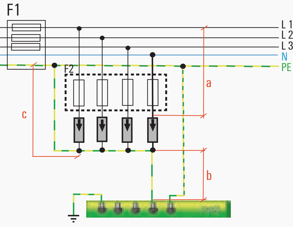
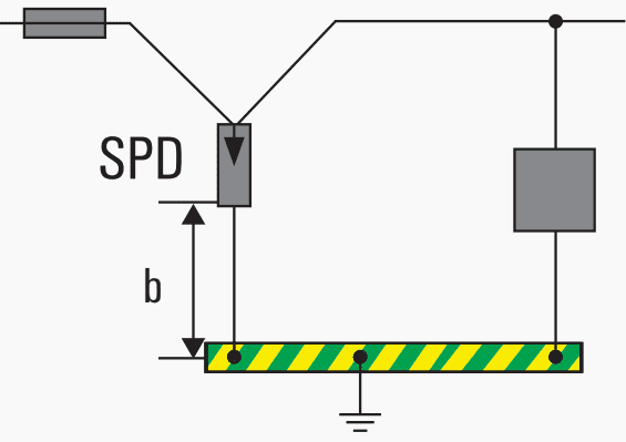
5.5 Cable lengths
A) It is valid: a + c ≤ 0.5 m / 20 inch, then b is not relevant
Figure 14 – Cable lengths (a + c ≤ 0.5 m / 20 inch)
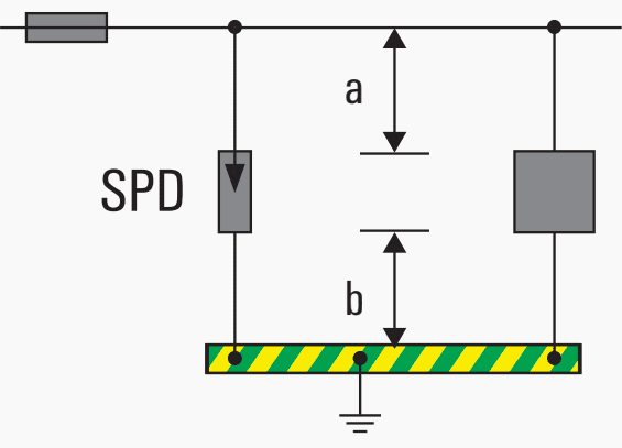
B) It is valid: a + b ≤ 0.5 m / 20 inch
Figure 15 – Cable lengths (a + b ≤ 0.5 m / 20 inch)
C) It is valid: b ≤ 0.5 m / 20 inch
Figure 16 – Cable lengths (b ≤ 0.5 m / 20 inch)
Go back to the Contents Table ↑
5.6 Fuse protection
Surge protection devices for instrumentation and control systems frequently operate with a decoupling between the components. This decoupling is carried out using inductors or resistors. The decoupling dictates the cable type, cable routing and also a fusing for the maximum nominal current of the surge protection devices.
In the event of overloads caused by partial lightning currents or transformer short circuits, the lightning arrester and surge arrester (SPD) must be protected by a back-up fuse if F1 is greater than the value specified by the manufacturer.
In compliance with the ratio 1:1.6, the maximum nominal value should be configured for the SPD. Depending on the installation of the connecting cables, F1 can be increased during the lifespan of the facility. If a circuit breaker or a main circuit breaker is used instead of the safety fuse required in the installation instructions, then the triggering characteristics must be followed.
Suggested reading – Dos and don’ts in operating LV/MV circuit breakers, relays, disconnectors and fuses
Dos and don’ts in operating LV/MV circuit breakers, relays, disconnectors and fuses
Go back to the Contents Table ↑
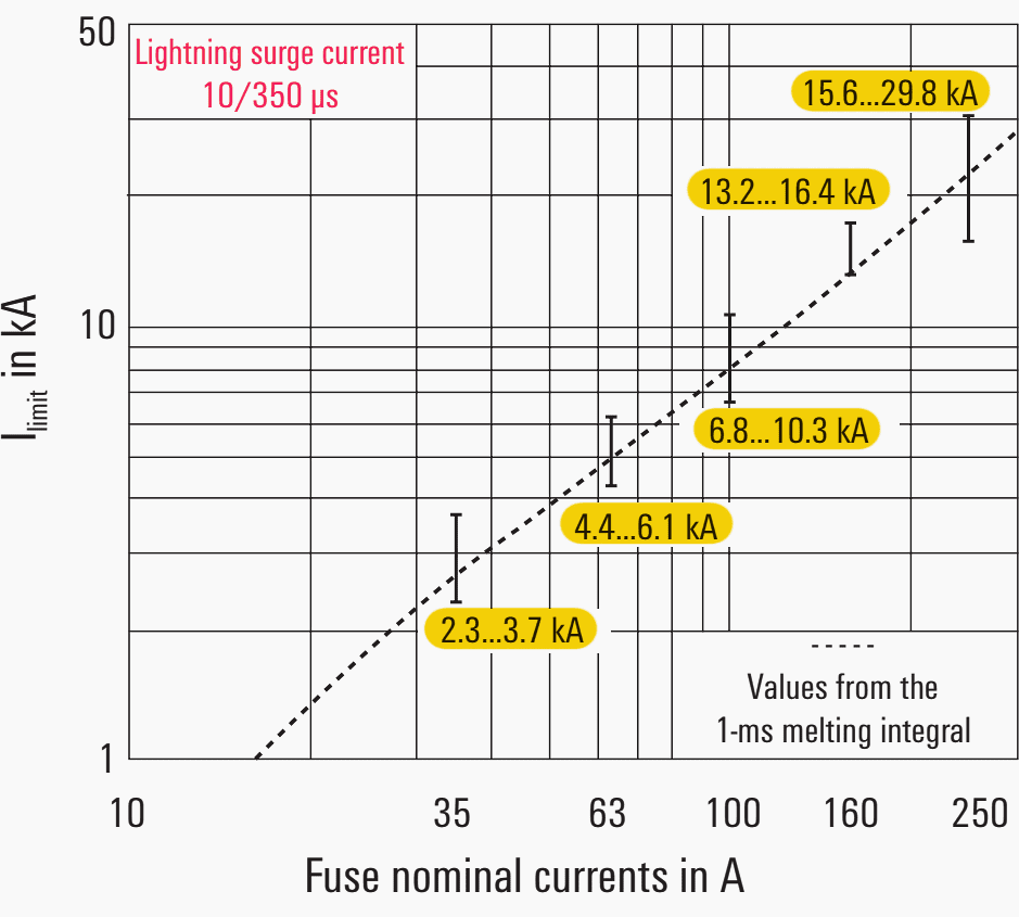
5.7 Lightning current strength of NH fuses
5.7.1 for surge currents 10/350 μs
Figure 17 – Lightning current strength of NH fuses for surge currents 10/350 μs
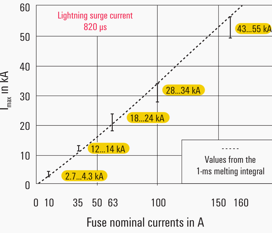
5.7.2 For surge currents 8/20 μs
Figure 18 – Lightning current strength of NH fuses for surge currents 8/20 μs
Go back to the Contents Table ↑
5.8 Behaviour of NH fuses for lightning surge current (10/350 µs)
It is important to understand that the question is not how small the SPD fusing should be; rather the maximum backup fuse that should be used, as the capacity of the small fuses to carry lightning current is very limited.
Unrestricted SPD protection is only available when the installation accommodates the maximum value.
Figure 19 – Nominal current and design of NH fuses
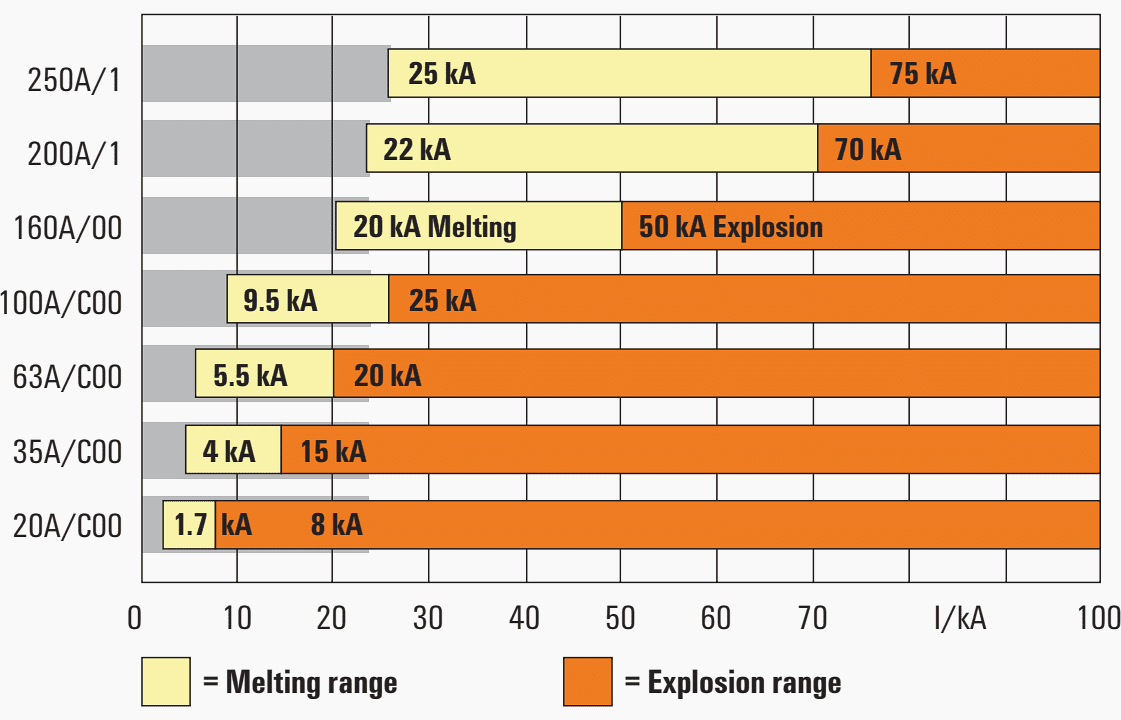
Figure 20 – Installation of the lightning and surge protection devices in electrical panel
Go back to the Contents Table ↑
Source: Weidmüller
Related electrical guides & articles


Edvard Csanyi
Hi, I'm an electrical engineer, programmer and founder of EEP - Electrical Engineering Portal. I worked twelve years at Schneider Electric in the position of technical support for low- and medium-voltage projects and the design of busbar trunking systems.I'm highly specialized in the design of LV/MV switchgear and low-voltage, high-power busbar trunking (<6300A) in substations, commercial buildings and industry facilities. I'm also a professional in AutoCAD programming.
Profile: Edvard Csanyi
