
VFT overvoltages
The level reached by very fast transients (VFT) overvoltages originated by disconnector switching or line-to-ground faults inside a gas insulated switchgear (GIS) are below the basic insulation level (BIL) of substation and external equipment.
However, aging of the insulation of external equipment due to frequent VFT must be considered.
Transient enclosure voltages (TEV) is a low energy phenomenon and it is not considered dangerous to humans; the main concern is in the danger of the surprise-shock effect. External transients can cause interference with or even damage to the substation control, protection, and other secondary equipment.

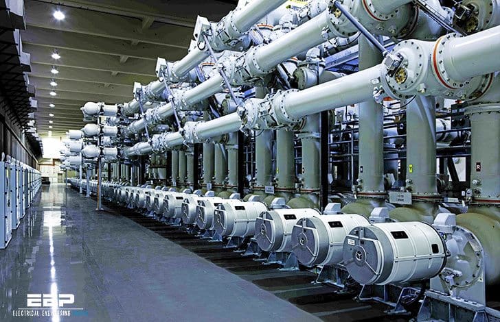
SF6 insulation
Breakdown caused by VFT overvoltages is improbable in a well-designed GIS insulation system during normal operations.
However, at ultra high voltage systems, more than 1000 kV, for which the ratio of BIL to the system voltage is lower, breakdown is more likely to be caused. At these levels, VFT overvoltages can be reduced by using resistor-fitted disconnectors.
Transformers
Due to steep fronted wave impulses, direct connected transformers can experience an extremely nonlinear voltage distribution along the high-voltage winding, connected to the oil-SF6 bushings, and high resonance voltages due to transient oscillations generated within the GIS.
Transformers can generally withstand these stresses. However, in critical cases, it may be necessary to install varistors to protect tap changers.
Disconnectors and breakers
The insulation system of breakers and switches is not endangered by VFT overvoltages generated in adjacent GIS equipment. Ground faults induced by VFT overvoltages have been observed in disconnectors operations, as residual leader branches can be activated by enhanced field gradient to ground.
Enclosure
Transient enclosure transients (TEV) can:
- Cause sparking across insulated flanges and to insulated busbars of CTs, and
- Can puncture insulation that is intended to limit the spread of circulating currents within the enclosure.
TEV can be minimized with a proper design and arrangement of substation masts, keeping ground leads as short and straight as possible in order to minimize the inductance, increasing the number of connections to ground, introducing shielding to prevent internally generated VFT from reaching the outside of the enclosure, and installing voltage limiting varistors where spacers must be employed.
Bushings
Very few problems have been reported with capacitively graded bushings. High impedances in the connection of the last graded layer to the enclosure should be avoided.
Secondary equipment
TEV may interfere with secondary equipment or damage sensitive circuits by raising the housing potential if they are directly connected, or via cable shields to GIS enclosure by emitting free radiation which may induce currents and voltages in adjacent equipment.
The coupling of radiated energy may be reduced by mounting control cables closely along the enclosure supports and other grounded structures, grounding cable shields at both ends by leads as short as possible, or using optical coupling services. Voltage limiting devices may have to be installed.
Reference: The Electric Power Engineering Handbook – Ed.L.L. Grigsby (Get hardcopy from Amazon)


You should be using EMC solution from Roxtec. The tests have been done and it has been proved that effects from VFTO can be cut down by approx. 60%.