
Estimated Study Time: 7 minutes
Introduction
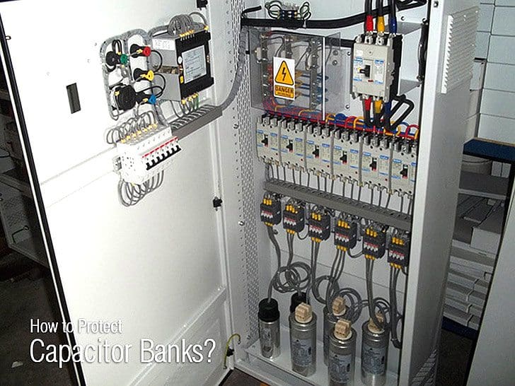
Capacitor banks are used to compensate for reactive energy absorbed by electrical system loads, and sometimes to make up filters to reduce harmonic voltage. Their role is to improve the quality of the electrical system. They may be connected in star, delta and double star arrangements, depending on the level of voltage and the system load.
A capacitor comes in the form of a case with insulating terminals on top. It comprises individual capacitances which have limited maximum permissible voltages (e.g. 2250 V) and are series-mounted in groups to obtain the required voltage withstand and parallel-mounted to obtained the desired power rating.

There are two types of capacitors:
- Those with no internal protection,
- Those with internal protection: a fuse is combined with each individual capacitance.
Types of faults
The main faults which are liable to affect capacitor banks are:
- Overload,
- Short-circuit,
- Frame fault,
- Capacitor component short-circuit
1. Overload
An overload is due to temporary or continuous overcurrent:
Continuous overcurrent linked to:
- Raising of the power supply voltage,
- The flow of harmonic current due to the presence of non-linear loads such as static converters (rectifiers, variable speed drives), arc furnaces, etc.,
Temporary overcurrent linked to the energizing of a capacitor bank step. Overloads result in overheating which has an adverse effect on dielectric withstand and leads to premature capacitor aging.
2. Short Circuit
A short-circuitis an internal or external fault between live conductors, phase-to-phase or phase-to-neutral depending on whether the capacitors are delta or star-connected.
The appearance of gas in the gas-tight chamber of the capacitor creates overpressure which may lead to the opening of the case and leakage of the dielectric.
3. Frame fault
A frame fault is an internal fault between a live capacitor component and the frame created by the metal chamber.
Similar to internal short-circuits, the appearance of gas in the gas-tight chamber of the capacitor creates overpressure which may lead to the opening of the case and leakage of the dielectric.
4. Capacitor component short-circuit
A capacitor component short-circuit is due to the flashover of an individual capacitance.
With no internal protection: The parallel-wired individual capacitances are shunted by the faulty unit:
- The capacitor impedance is modified
- The applied voltage is distributed to one less group in the series
- Each group is submitted to greater stress, which may result in further, cascading flashovers, up to a full short-circuit.
With internal protection: the melting of the related internal fuse eliminates the faulty individual capacitance: the capacitor remains fault-free, its impedance is modified accordingly.
Protection devices
Capacitors should not be energized unless they have been discharged. Re-energizing must be time-delayed in order to avoid transient overvoltage. A 10-minute time delay allows sufficient natural discharging.
Fast discharging reactors may be used to reduce discharging time.
Overloads
Overcurrent of long duration due to the raising of the power supply voltage may be avoided by overvoltage protection that monitors the electrical system voltage. This type of protection may be assigned to the capacitor itself, but it is generally a type of overall electrical system protection.
Given that the capacitor can generally accommodate a voltage of 110% of its rated voltage for 12 hours a day, this type of protection is not always necessary.
- Thermal overload
- Time-delayed overcurrent
provided it takes harmonic frequencies into account.
The amplitude of overcurrent of short duration due to the energizing of capacitor bank steps is limited by series-mounting impulse reactors with each step.
Short circuits
Short-circuits are detected by a time-delayed overcurrent protection device. Current and time delay settings make it possible to operate with the maximum permissible load current and to close and switch steps.
Frame faults
Protection depends on the grounding system. If the neutral is grounded, a time-delayed earth fault protection device is used.
Capacitor component short-circuits: Detection is based on the change in impedance created by the short-circuiting of the component for capacitors with no internal protection by the elimination of the faulty individual capacitance for capacitors with internal fuses.
When the capacitor bank is double star-connected, the unbalance created by the change in impedance in one of the stars causes current to flow in the connection between the netural points. This unbalance is detected by a sensitive overcurrent protection device.
Examples of capacitor bank protection
Double star connected capacitor bank for reactive power compensation

Filter

Setting information
| Type of fault | Setting |
| Overload | Overvoltage setting: ≤110% Vn Thermal overload: setting ≤1.3 In or overcurrent setting ≤1.3 In direct time or IDMT time delay 10 sec |
| Short-circuit | Overcurrent direct time setting: approximately 10 In time delay approximately 0.1 sec |
| Frame fault | Earth fault direct time setting: ≤20% maximum earth fault current and ≥10% CT rating if suppied by 3 CTs time delay approximately 0.1 sec |
| Capacitor component short circuit | Overcurrent direct time setting: < 1 ampere time delay approximately 1 sec |
Resource: Protection Guide – Schneider Electric
Related electrical guides & articles


Edvard Csanyi
Hi, I'm an electrical engineer, programmer and founder of EEP - Electrical Engineering Portal. I worked twelve years at Schneider Electric in the position of technical support for low- and medium-voltage projects and the design of busbar trunking systems.I'm highly specialized in the design of LV/MV switchgear and low-voltage, high-power busbar trunking (<6300A) in substations, commercial buildings and industry facilities. I'm also a professional in AutoCAD programming.
Profile: Edvard Csanyi

The scenario. An electrician opened the cabinet of a capacitor bank. When he closed the door and after he turn back and walked away. A few seconds later (8-10sec) A loud explosion was heard and a light spark has been observed by his companions inside the cabinet. When they opened the door of the cabinet, The main CB rated 800A was trip-off and a branck CB was trip-off. There was a dark traces of spark was seen at the side of the cabinet and on the main CB. The main CB was fine. It was re energized. What would be the cause?
How Series reactor value is calculated for 11kV Slip Ring Induction motors when used in conjunction with Capacitors
I HAVE SOME DOUGHT REGARDED TO CAPACITOR SELECTION.IS IT ELECTROLATIC CAPACITOR?
AND I USED CAPACITOR BANK FOR 230 VOLT AC THAN I ALSO HAVE ITS VOLTAGE RATING PLZ SEND DETAIL ON MY EMAIL ID
No, electrolitic capacitors are only used in DC, since it’s voltage has to be always positive. In MV systems we normally use AC so the capacitor must withstand 120 changes of polarity per second (60Hz systems).
Does available fault current on the bus the capacitor bank is connected to affect the fault current interrupting rating of the step/stage circuit breakers of the capacitor bank?
Regardless of the capacitor bank, the available fault current on the bus has to be taken into account for the rating of the CB.
Now, if your asking if the capacitor bank could increase the value of the available short circuit the answer is no. Actually, the capacitor “supplies” some current during a fault but the amount of power in the capacitor is so low that the effect is mitigated in a few microseconds, so you don’t need to consider it’s contribution.
Other important factor to consider is that capacitor bank are not always connected through a CB. A lot of times a “capacitor switch” is used (http://www.tnb.com/pub/en/node/547). This type of switches normally do not have short circuit capability and they have a sort of low “making current” value. So, if the short circuit level is high, perhaps the inrush current could damage the switch. This is easily fixed with an small series reactor )https://image.slidesharecdn.com/2011cedcapacitors-150502230214-conversion-gate01/95/capacitors-49-638.jpg?cb=1430607763)
Thanks for all a nice information about the magice of engineering
How to compute current load?
p.s. if we want talk about the protection of capacitor bank we should first talk about the switching of the capacitor bank in service and its inrush current then how to select a CB and HRC fuse for this unit then talk about the effect of the harmonics on the capacitor bank and how to select those filters then talk about different capacitor bank configuration and how to protect each configuration then make the case more practical by selecting a protection unit and how did we select each of its control parameter ……. thanks for the effort you made on your article
pls reply to my mail sir [email protected]
while doing motor commissioning of 500 hp the motor started very well with power factor of o.8 but when we charged the capacitor bank all the breakers tripped suddenly and fuse is also blow out in DP structure pls can you tell me the why we cannot charge capacitor bank when the motor is running…
Thank you.
Can you provide me more information, circuit breakers rated currents, rated voltage and size of capacitor banks. It’s very hard to tell you, it could happen many things. Is all equipment selected correctly?
One question: if a cell is damaged and the internal fuse blows the voltage across the other groups/cells will raise.
How do you monitor the overvoltage on the other groups/cells considering the manufacturers states that 10% overvoltage wil let normal life of the capacitor fall to 50%?
The main circuit breaker of the capacitor banks group will trip for sure. Protection unit of CB won’t let 10% overvoltage unless it’s already set like this, but I dult in this.