Switching duties of a CBs
With the phenomenal growth of the power system (EHV and HV) the duties that a circuit breaker is called upon to perform, besides the ability to handle short circuits, have become complex. Recent studies in this field have thrown much light on switching duties, which often place severe demands on the breakers.

This technical article explains the six most important HV/EHV circuit breaker duties.
They are:
- Terminal faults
- Short line faults
- Transformer magnetising and reactor currents
- Energization of long transmission lines
- Switching of unloaded transmission lines and capacitor banks
- Out of phase switching
In each of the above-mentioned switching duties, the shape of the transient recovery voltage is largely influenced by a number of network parameters. The influence of these parameters has been described below, with reference to each duty.
1. Terminal Faults
Usually the short-circuit current is inductive in nature, and the re-strike voltage appearing across the contacts at the instant of arc interruption is characterized by high-frequency oscillations in the order of a few hundred cycles.
The magnitude of severity imposed on the circuit breaker depends on this frequency and the peak value of voltage.
1.1 Transient Recovery Voltage
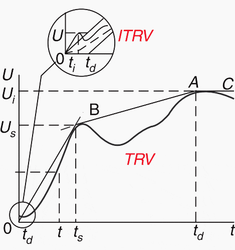
The transient recovery voltage is the actual voltage appearing across the circuit breaker contacts immediately after the arc interruption.
The voltage will, of course, ultimately approach the open-circuit voltage, but will do so in the form of high-frequency voltage oscillation governed by the circuit parameters ‘L’ and ‘C’. This Recovery voltage is given by:
e(1 – cos (t/√(L×C)))
The maximum transient recovery voltage is twice e. The resistance present in the circuit damps this transient voltage.
The Transient recovery voltage after short circuit interruption is shown in Figure 1a.


To test the breaker, a six parameter method is applied, as shown in Figure 1b.

1.2 Power Frequency Recovery Voltage
The power frequency recovery voltage is basically equal to the open-circuit voltage of the network in the open position of the circuit breaker. Immediately after a fault is cleared in a three-phase circuit, the power frequency voltage differs in the different phases, usually being highest in the first phase.
If the network-neutral is not earthed, the voltage across the first pole to be cleared is 1.5×U, where U is the phase voltage.
In an earthed neutral system, the voltage across the first pole to clear will be approximately 1.3×U.
Airblast circuit breakers are the most sensitive to the shape of the TRV, because the heavily ionized air de-ionizes very slowly, and thus takes a comparatively long time to regain its insulation level.
It is often necessary to provide such breakers with low ohm breaking resistors, in order to reduce the RRRV. On the other hand, the air blast circuit breakers are less sensitive to the initial transient recovery voltage (ITRV) because of a comparatively high arc voltage.
SF6 breakers are less sensitive to the shape of the TRV because SF6, an electronegative gas, has ions that re-combine faster than in air.
However, the comparatively low arc voltage makes them more sensitive to the ITRV, and the shape of the initial voltage determines the breaking capacity of these circuit breakers.
Bulk oil and minimum oil circuit breakers are inherently sensitive to RRRV and to ITRV. In these circuit breakers, the arc burns in heavily pressured hydrogen, which quickly regains its di-electric strength after current zero.
The ability to cope with the ITRV is further enhanced by the occurrence of a comparatively high arc voltage immediately prior to current zero.
2. Short Line Faults (SLF)
Short-circuit faults occurring on a line length between 0.5 to 5 km are termed as short line faults or kilometric faults. A fault of this type imposes a highly onerous duty on the circuit breaker, thereby affecting its interrupting ability.
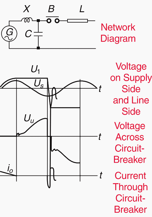
On the supply side, the voltage will oscillate at the supply frequency ultimately approaching the open-circuit voltage. On the line side of the circuit breaker, the trapped charges, after the interruption, initiate traveling waves on the transmission line, and these waves impose a saw tooth waveform at the circuit interruption. Since there is no driving voltage on the driving side, the voltage ultimately becomes zero because of the line losses.
The network diagram, and the line side and supply side voltage waveforms are shown in Figure 2 below.


Even though the magnitude of the voltage oscillation is considerably lower than that of the system voltage, the frequency is very high. This means that the RRRV across the circuit breaker can be much higher than the terminal short-circuit cases. Even though the short-circuit current is quite less, the high RRRV may cause the interrupter to fail.
Thus, for an EHV circuit breaker, which is sensitive to RRRV, there may be a critical line length, which imposes the most severe duty on the breaker.
As in the case of the terminal fault, the use of the damper resistors reduces the RRRV. Since the SLF represents a case with very high RRRV, it is quite natural that the air blast circuit breaker will face difficulties with the interruption. Low ohm resistors are thus usually necessary.
SF6 circuit breakers are highly sensitive to the high voltage rates of rise during the first few micro-seconds of the current zero. SF6 gas breakers can easily handle the high RRRV in case of SLF duty, as the dielectric strength of the gas is very high.
3. Transformer Magnetizing and Reactor Currents
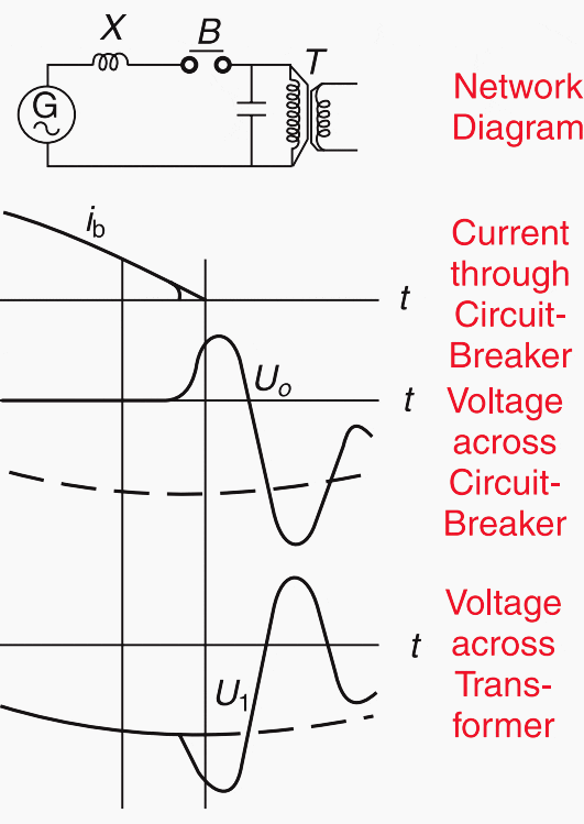
The transformer no-load current and the reactor current impose severe stresses on the circuit breaker upon their interruption because of the low magnitude of these inductive currents. In the case of externally generated pressure, there is a tendency for the current to be forced to zero before its natural zero.
Depending on the dielectric strength of the gap, re-ignitions or re-strikes may occur before the maximum voltage can be reached. As soon as the arc is re-struck it is immediately chopped again, but as the current has decreased during this time, a lower prospective voltage will be induced.
Overvoltages, of the order of 2.5 to 3.5 times the rated voltages, are encountered in normal practice. The basic phenomenon of current chopping is shown in Figure 3.

The interruption of the reactor current also has the same effect except that the severity on the breaker is more compared to magnetizing current. This is so because in breaking the transformer current, only part of stored energy is released due to the hysteresis and other losses, but in the case of reactor current, the complete energy is released.
In turn, the overvoltages generated in reactor switching are higher.
Severity of over-voltages is less in the case of a self-generated pressure circuit breaker (the pressure generated is proportional to the current interrupted), compared with the externally generated pressure breaker (the pressure is independent of the current).
High voltage transformers are fitted with surge arresters for protection against switching overvoltages. The overvoltages produced due to current chopping are high in gas blast breakers, as the gas blast is normally dimensioned for heavy short-circuit currents. Minimum oil circuit breakers on other hand, generate their own pressure, the magnitude of which is related to the magnitude of the current interrupted.
Current chopping is associated with the switching of reactors, minimum oil circuit breakers, pressurised breaker units, and puffer type SF6 circuit breakers.
However, field and laboratory tests conducted on such circuit breakers, without any special means for surge reduction, have shown voltages much less than 1.5 times the rated voltages.
4. Energization of Long Transmission Lines
When an initially uncharged, unloaded long line is charged, then over-voltages to the order of twice the normal voltage are impressed, imposing an onerous duty on the power system. Higher voltages can occur if the line has trapped charges. When a line is switched on to an energized network, a voltage wave is impressed on it. The impressed wave will be reflected at the far end of the line, and if this is open, the voltage will increase two-fold.
In the case of the three-phase circuit, the situation becomes more severe if the circuit breaker poles do not close simultaneously. The wave on one phase will produce an induced wave on the other phase.
With the help of pre-insertion resistors, the switching voltages can be reduced to less than 2 p.u.


The best method of reducing the over-voltages generated on the energization of the lines is to equip the circuit breaker with pre-insertion resistors (see Fig. 4), to ensure that the closing takes place in two stages.
In the first stage, the resistor is included in series with the line to damp the waves. In the second stage, the resistor is short-circuited. The optimum value of the pre-insertion resistance is usually of the same order of magnitude as that of the surge impedance of the line and the insertion time should be at least 10 milliseconds.
The switching over-voltages occurring with energisation and re-energisation of the lines are caused by the system phenomenon and are thus independent of the circuit breaker used. Other means like the controlled synchronous closing of the circuit breaker poles can also be used.
5. Switching of Unloaded Transmission Lines and Capacitor Banks
The disconnection of long unloaded line involves the interruption of large capacitive current. Interruption takes place at the natural zero of the current, i.e. when the voltage is at its maximum. After interruption, a direct voltage remains on the line. This disappears slowly, whereas the voltage on the supply side of the circuit breaker continues to vary with the system frequency.
If the discharge current is interrupted at its first current zero, a direct voltage, now with opposite polarity and with twice the amplitude as before will remain on the line.
After a further half cycle, the voltage across the circuit breaker may increase to three times the phase voltage with the risk of another re-strike and further escalation of the voltage on the line.

Circuit breakers with externally generated pressure are practically re-strike free when interrupting capacitive currents. An air blast circuit breaker is a good example. On the other hand, the circuit breakers with self-generated pressure like bulk oil and minimum oil circuit breakers might re-strike, resulting in over-voltages.
The reasons being that the capacitive currents are of small magnitude, generate low pressure to make the breaker re-strike free.
This problem can be solved by slightly pressurising the interrupting units with nitrogen thereby rendering them re-strike free when dealing with capacitive currents. SF6 gas puffer circuit breakers have a low probability of restrike in case of line charging application.
6. Out of Phase Switching
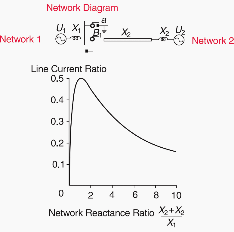
An important requirement to be considered for the circuit breaker regarding interconnection between two different generating systems, is the ability of the circuit breaker to open the circuit when the two systems fall out of synchronism.
For the circuit breaker (B1) in station 1, (see Figure 6) this case occurs if X2 + XL = X1, i.e. if the short-circuit power transmitted from network 2 equals the short-circuit power of network 1.
However this is not a realistic case, because the transmission line in most cases will considerably reduce the power from network 2 as also the current. Studies carried out in different countries show that the current under out of phase conditions never exceed 25 per cent of the rated short-circuit current of the circuit breaker.
Hence the relevant IEC standard recommends testing at 25% of the rated short-circuit current.

The recovery voltage across a single pole of the circuit breaker can be assumed to be twice the rated phase to earth voltage, if the system neutral is directly earthed, and 2.5 times the phase voltage if the system neutral is not earthed. These values apply to out of phase switching without any prevailing fault on the system.
Out of phase switching must be avoided as far as possible in systems and this can be achieved by proper relaying. Circuit breakers are normally tested for out of phase conditions.
Sources:
- Switchgears book by BHEL – Bharat Heavy Electricals Limited
- Use of a Pre-Insertion Resistor to Minimize Zero-Missing Phenomenon and Switching Overvoltages by F. Faria da Silva, C. L. Bak, U. S. Guðmundsdóttir, W. Wiechowski and M. R. Knardrupgård




Useful technical literature on Switching technologies:
https://www.amazon.com/Switching-Electrical-Transmission-Distribution-Systems/dp/1118381351
https://fliphtml5.com/dfbj/phog/basic
https://ieeexplore.ieee.org/stamp/stamp.jsp?tp=&arnumber=7089124
Dear Sir,
I appreciate you to consider for premium member.
Dear Sir,
Your papers are worth reading but I have requested my office to consider my request for reimbursement for premium membership. It might take about a month.