
Estimated Study Time: 27 minutes
Substation auxiliary facilities
Nowadays, HV/EHV substations have become pretty complex from the design point of view. Besides the main electrical equipment, which must be designed and selected correctly, there are several auxiliary facilities without which a substation would not be able to operate correctly and safely. Auxiliary facilities such as earthing, cabling, oil handling system, lighting, fire fighting, crane and other unloading facilities, oil filtration, AC/DC auxiliary system, etc., must be provided.
 The essential HV/EHV substation auxiliary facilities you should know about
These requirements have been briefly discussed in this technical article.
- Earthing
- Cabling
- Oil-handling system
- Illumination system
- Crane facilities
- Fire protection facilities
- DC auxiliary supply
- AC auxiliary supply
- Ventilation
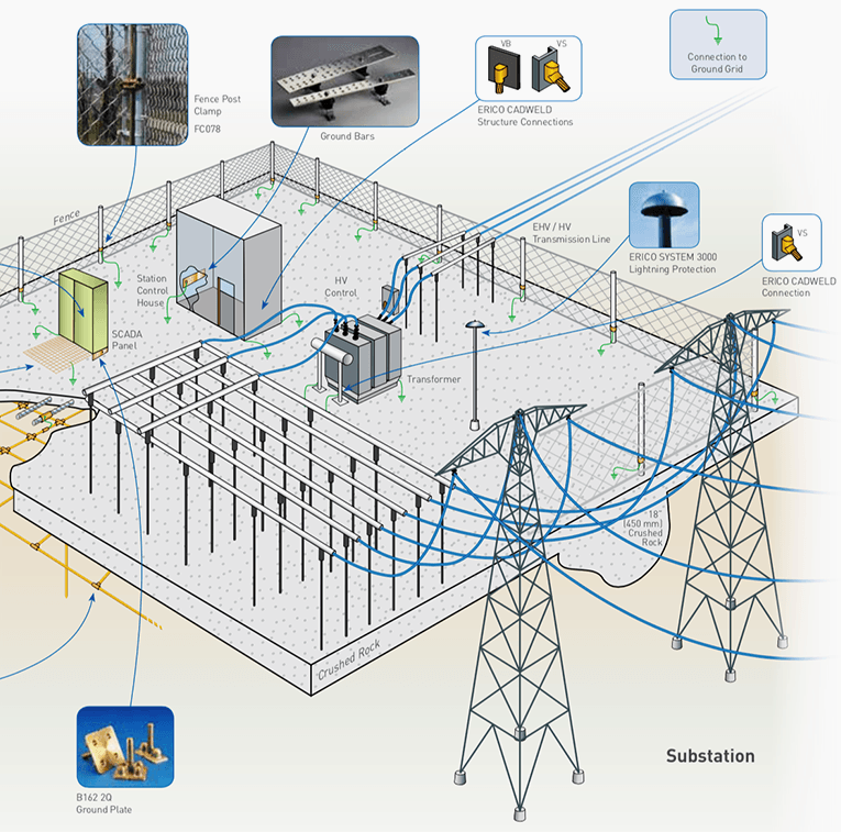
1. Earthing
Provision of adequate earthing system in a substation is extremely important for safety of the operating personnel as well as for proper system operation and performance of the protection devices.
The primary requirement of a good earthing system in a substation are:
- The impedance to ground should be as low as possible. In general it should not exceed 1 ohm for substations with high fault levels (EHV substation) and 5 ohms for substations with low fault levels (Distribution substation).
- The step and touch potentials should be within safe limits.
All the non-current carrying metal parts of the equipment in the substation are connected to the earthing mat so as to ensure that under fault conditions, none of these parts is at a potential higher than that of the earthing mat.
Under normal condition, the ground rods make little contribution in lowering the earth resistance. These are, however, helpful in maintaining low value of resistance under all weather conditions which is particularly important for installations with high system earth fault currents.
All substations should have provision for earthing the following:
- The neutral points of equipment in each separate system. There should be independent earth for the different systems. Each of these earthed points should be interconnected with the station earthing mat by two different diagonally opposite connectors to avoid common mode failure.
- Equipment framework and other non-current carrying metal parts.
- All extraneous metal frameworks not associated with equipment.
- Lightning arresters: These should have independent earthing which should in turn be connected to the station grounding grid or earthmat.
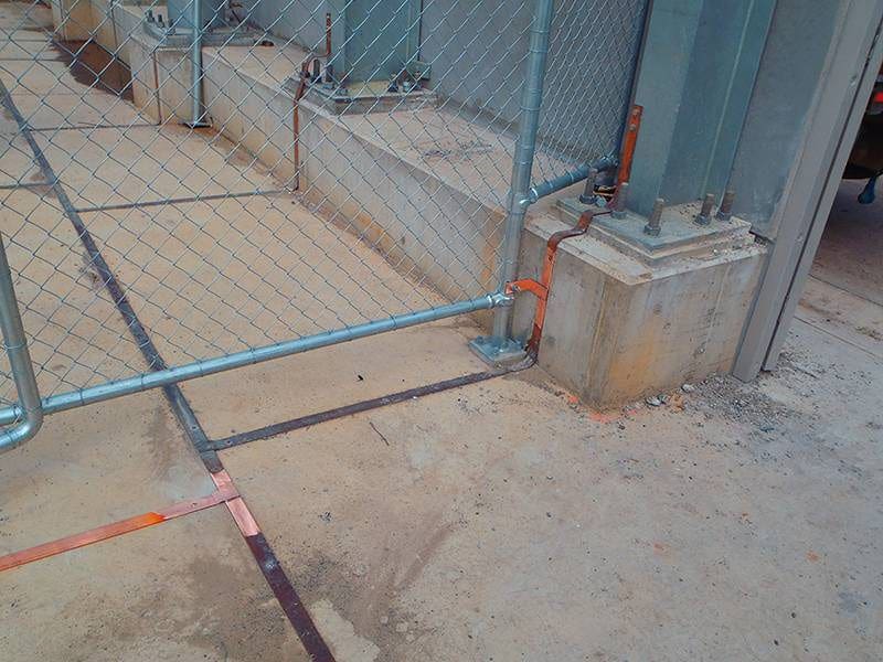
Where the fenced area is large and mat area is small, in that case fence earthing should be isolated from the main earth mat so that person touching the fence is protected from danger due to transfer voltage.
Earthing in a substation must conform to the requirements of IEEE Std 80. The earthing system should be designed to have low overall impedance, and a current carrying capacity consistent with the fault current magnitude.
The major parameters which influence design of earth mat are:
- Magnitude of fault current
- Duration of fault
- Soil resistivity
- Resistivity of surface material
- Shock duration
- Material of earth conductor, and
- Earth mat grid geometry
2. Cabling
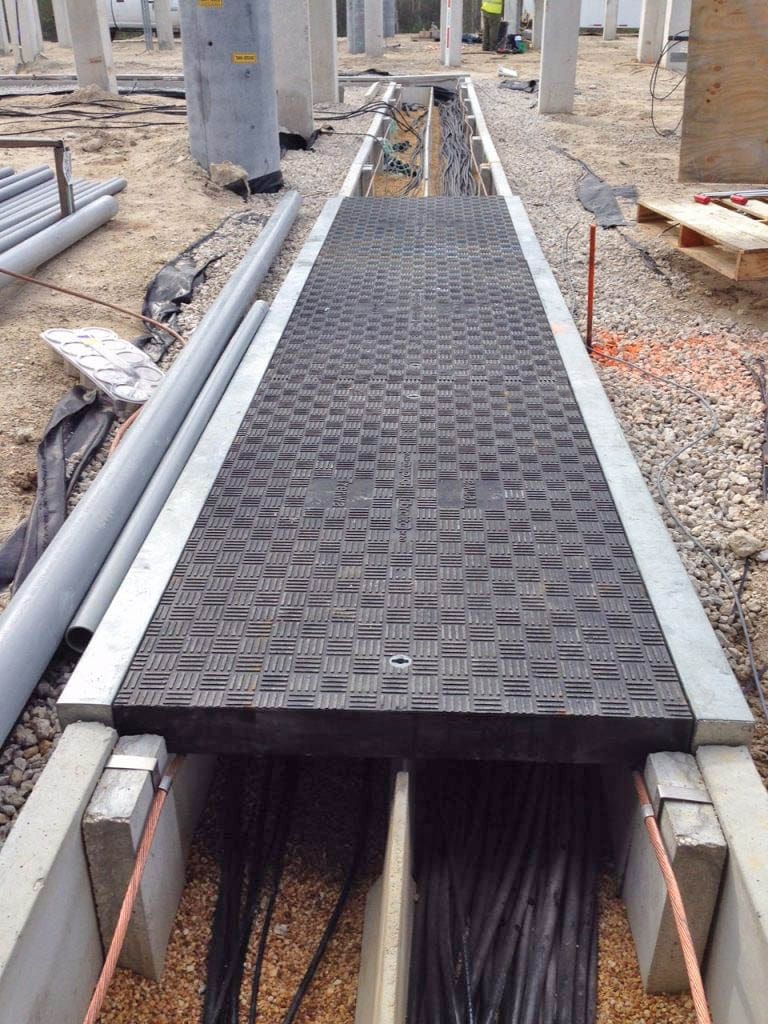
Trenches and cable ducts are normally laid for cable runs. In very large substations, particularly those associated with power plants, tunnels have also been used. Except where cables enter and take off from trench, directly buried cables are generally avoided to facilitate locating faults and rapidly restoring the supply.
The substation area should be properly graded so that the rainwater is drained away form the cables trenches. For draining off any water that may enter the trenches, these should be sloped in their run to drain freely and necessary arrangements made to remove the accumulated water as and when required.
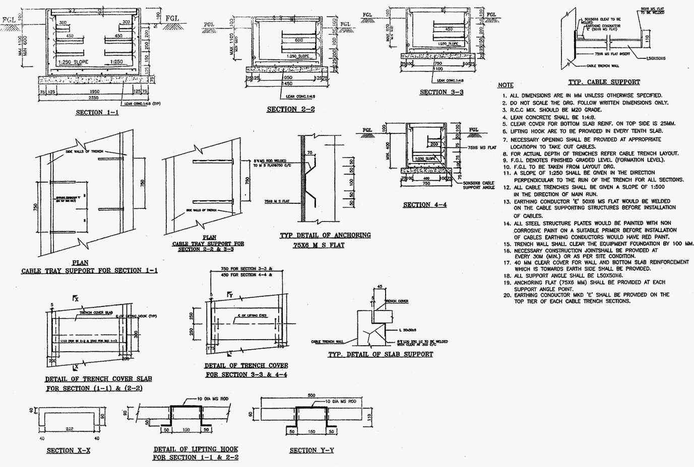
Cable trenches should be provided with strong and effective covers. Cables should not be laid directly in the trench floor. A typical cable trench is shown in Figure 3. At points of entry into indoor areas, termination chambers etc., waterproof and fireproof sealing arrangements should be made.
Conduits should have the minimum number of bends in their run. Pull boxes to facilitate cable pulling should be provided at suitable locations. Conduits should be sloped and drained at low points.
In indoor areas, cable may be laid in racks supported on walls, ceiling or floor, floor trenches or clamped to walls or ceiling. Wherever a large number of cables are involved and conditions so permit, a system of racks is preferable as it gives quick access. Particular care should be taken in substation design to permit easy entry of cable in to switchgear with convenience of handling even afterwards.
Cable laying should be done in accordance with systematically prepared cable schedules. In major substation thousands of separate cables will be involved and quick tracing of defects will depend very much on the orderliness exercised while laying. All cable ends should be suitably labeled to facilitate easy identification.
IMPORTANT! – Power cables and control cables should be segregated by running in separate trenches or on separate racks so that in the event of a fire, the control cables are not affected.
Segregation of AC and DC control cables to the extent possible is also useful. Separate cables should be used for each CT and PT.
Related electrical guides & articles


Edvard Csanyi
Hi, I'm an electrical engineer, programmer and founder of EEP - Electrical Engineering Portal. I worked twelve years at Schneider Electric in the position of technical support for low- and medium-voltage projects and the design of busbar trunking systems.I'm highly specialized in the design of LV/MV switchgear and low-voltage, high-power busbar trunking (<6300A) in substations, commercial buildings and industry facilities. I'm also a professional in AutoCAD programming.
Profile: Edvard Csanyi
