
Estimated Study Time: 8 minutes
HV electrical measurements
Electrical measurements on a high-voltage transmission and distribution systems cannot be made practically or safely with direct contact to the power carrying conductors. Instead, the voltages and currents must be brought down to a safe and usable level that can be input into measuring instruments.
This is the whole point task of an instrument transformers CTs and VTs.
They provide replica voltages and currents scaled to more manageable levels. They also bring their replicas to a safe ground potential reference. The most common output range 0 – 5.0 A for currents based on their nominal inputs. Other ranges are used as well.
The majority of these devices are iron core transformers.
Current Transformers
Current transformers (CTs) of all sizes and types find their way into substations to provide the current replicas for metering, controls, and protective relaying. Some will perform well for SA applications and some may be marginal.
CT performance is characterized by:
- Turns ratio,
- Turns ratio error (ratio correction factor),
- Saturation voltage,
- Phase angle error, and
- Rated secondary circuit load (burden).
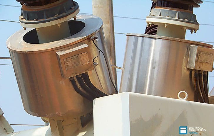
CTs are often installed around power equipment bushings, as shown in Figure 1 below:

They are the most common types found in medium voltage and high voltage equipment. Bushing CTs are toroidal, having a single primary turn (the power conductor), which passes through their center. The current transformation ratio results from the number of turns wound on the core to make up the primary and secondary.
Their ratio is the number of secondary turns divided by the number of primary turns. CT secondary windings are often tapped to provide multiple turns ratios. The core cross-sectional area, diameter, and magnetic properties determine the CT’s performance.
As the CT is operated over its nominal current ranges, its deviations from specified turns ratio are characterized by its ratio correction curve sometimes provided by the manufacturer. At low currents, the exciting current of the iron core causes ratio errors that are predominant until sufficient primary magnetic flux overcomes the effects of core magnetizing.
Thus, watt or var measurements made at very low load may be substantially in error both from ratio error and phase shift. Exciting current errors are a function of individual CT construction. They are generally higher for protection CTs than revenue metering CTs by design.
Revenue metering CTs are designed with core cross sections chosen to minimize exciting current effects and their cores are allowed to saturate at fault currents. Protection CTs use larger cores as high current saturation must be avoided for the CT to faithfully reproduce high currents for fault sensing.
The exciting current of the larger core at low primary current is not considered important for protection but can be a problem for measuring low currents. Core size and magnetic properties determine the ability of CTs to develop voltage to drive secondary current through the circuit load impedance (burden).
This is an important consideration when adding SA IEDs or transducers to existing metering CT circuits, as added burden can affect accuracy. The added burden of SA devices is less likely to create metering problems with protection CTs at load levels, but could have undesirable effects on protective relaying at fault levels. In either case, CT burdens are an important consideration in the design.
Experience with both protection and metering CTs wound on modern high silicon steel cores has shown, however, that both perform comparably once the operating current sufficiently exceeds the exciting current if secondary burden is kept low.

CT secondary windings are generally uncommitted.
They can be connected in any number of configurations so long as they have a safety ground connection to prevent the windings from drifting toward the primary voltage. It is common practice to connect CTs in parallel so that their current contribution can be summed to produce a new current such as one representing a line current where the line has two circuit breaker connections such as in a ‘‘breaker-and-a-half ’’ configuration.
However, new technology has developed, which makes it possible for an IED to compensate for CT performance limitations.
This technology allows the IED to ‘‘learn’’ the properties of the CT and correct for ratio and phase angle errors over the CT’s operating range. Thus, a CT designed to feed protection devices can be used to feed revenue measuring IEDs and meet the requirements of IEEE Standard C57.13.
Occasions arise where it is necessary to obtain current from more than one source by summing currents with auxiliary CTs.
There are also occasions where auxiliary CTs are needed to change the overall ratio or shift phase relationships from a source from a wye to a delta or vice versa to suit a particular measuring scheme. These requirements can be met satisfactorily only if the auxiliaries used are adequate. If the core size is too small to drive the added circuit burden, the auxiliaries will introduce excessive ratio and phase angle errors that will degrade measurement accuracy.
Using auxiliary transformer must be approached with caution.
Resource: Automation and the Substation – James W. Evans, The St. Claire Group, LLC
Related electrical guides & articles


Edvard Csanyi
Hi, I'm an electrical engineer, programmer and founder of EEP - Electrical Engineering Portal. I worked twelve years at Schneider Electric in the position of technical support for low- and medium-voltage projects and the design of busbar trunking systems.I'm highly specialized in the design of LV/MV switchgear and low-voltage, high-power busbar trunking (<6300A) in substations, commercial buildings and industry facilities. I'm also a professional in AutoCAD programming.
Profile: Edvard Csanyi

Dear Sir,
Ahmed from GE Egypt
please be informed that we need current transformer ring type 123 KV and 36 KV using for neutral point of power transformer 125 MVA
Ration: 1000 :2000
Class :PX
EK > 500 to 1000 V
Ik at Ek < 60 -30 mA
R < 3.5 to 7 ome
please check and if available , please send all data require to send your offer
i think you are doing great job. thank you
Thank you Charid!
Hello
I am an electrical engineer
If you please
Information or articles related to the current transformer to send me
Thank you
If I have a 1500/5 CT installed and only 100 amps flowing thru the secondary would this effect the accuracy of the metering device readings?
i wont to lern mor informetion.thank u.
Dear Mr. Advard,
Your efforts regarding the sharing of electrical knowledge is worth appreciable. I would request to please also share if you have any material regarding the sizing calculations of different CT types according to IEC standards.
Thank you.
Dear Mr.Edward
First of all i apreciate you for all your usefull articles,More over i need some information about instrument transformer to be used in GIS system and SF6 media specially for voltage transformer and practical aspect,if any.
Thank you in advance and with
Best Regards
D.Khalvati
thank u very very much Mr Evard
You’re welcome Omeralnahi, glad you like the article!