Substation elements
High voltage substations are pretty complex to understand since they have a way too many elements and each element is complex for itself and it depends on many system parameters and other elements. This technical article will shed some light on these elements, their graphic presentation as well as their brief description and the most common substation connection schemes they usually appear.
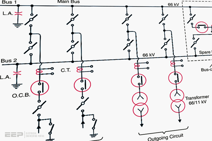
Note that described elements described are the main ones. There are many variations and combinations of equipment for example switch disconnectors or circuit breakers, combined CTs and Vts into one, digital protection relays and so on.
Nowadays, all these elements are getting more and more advanced and technically better, but the core base is the very same as they were 30 years ago. Working principles are the same.
So, let’s get into core substation elements!
- Graphic symbols of substation elements
- Equipment in power substation
- Busbar arrangements in substations
1. Graphic symbols of substation elements
Substations are usually presented using various elements (e.g. power transformers, circuit breakers, isolators, instrument transformers CTs, VTs etc.) by their graphic symbols in the connection schemes.
Symbols of the most important equipment in transformer substation are given below. Note that these symbols might not look the same depending on the standard applied (NEMA or ANSI).
Busbars


Single-break isolating-switch


Double-break isolating-switch


On-load isolating switch


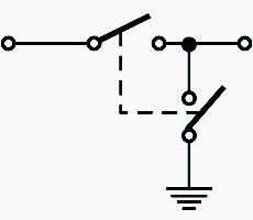
Isolating switch with earth blade

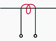
Current transformer (CT)

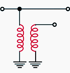
Potential (voltage) transformer (PT or VT)

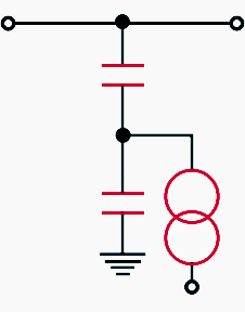
Capacitive voltage transformer (CVT)

Oil circuit breaker


Air circuit breaker with overcurrent tripping device


Air-blast circuit breaker
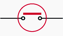

Lightning arrester (active cap)
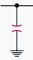

Lightning arrester (valve type)
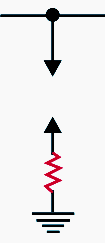

Arcing horn
![]()
![]()
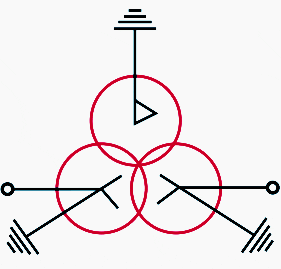
Three-phase transformer

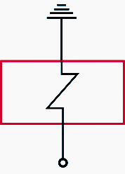
Overcurrent relay
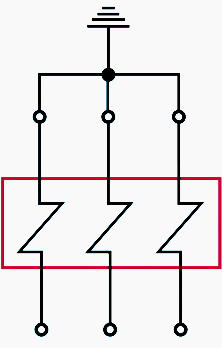

Earth fault relay

2. Equipment in power substation
The equipment required for a power substation depends upon the type of substation, service requirement and the degree of protection desired.
However, in general, high voltage substation has the following main equipment:
2.1 Busbars
A busbar structure is an assembly of bus conductors with associated connection joints and insulating supports. It can have bare or insulated conductors. A busbar is a grounded metal enclosure, containing factory-mounted, bare or insulated conductors, which are usually copper or aluminum bars, rods, or tubes (generally of rectangular x-section).
The most commonly used busbar arrangements in substations are:
- Single busbar arrangement
- Single busbar system with sectionalisation
- Double busbar arrangement
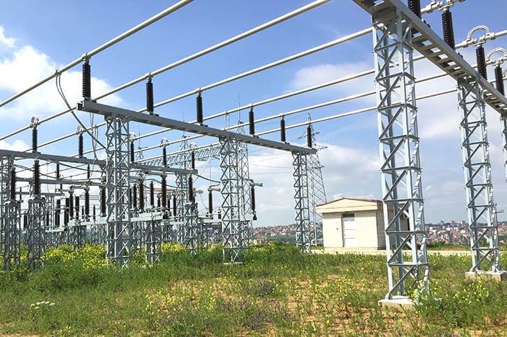

A detailed discussion on these busbar arrangements are discussed later.
Rigid busbar for 330kV substation (VIDEO)
2.2 Insulators
The insulators serve two purposes. They support the conductors (or busbars) and confine the current to the conductors. The most commonly used material for the manufacture of insulators is porcelain.
For example, post insulator is used for busbars. A post insulator consists of a porcelain body, cast iron cap and flanged cast iron base. The hole in the cap is threaded so that busbars can be directly bolted to the cap.
Insulators are such equipment that should be regularly examined for cracks, chips, breaks, and evidence of tracking or flashover.
Bad insulators MUST be replaced. Insulators should be regularly cleaned to remove any contaminating materials that may be present. Any presence of an excessive amount of contamination MUST be reported to the supervisor as it may require corrective measures.
Also, mountings of insulators should be checked for evidence of rust and corrosion and to ensure proper alignment and securement. Ground connections must be tight.
2.3 Isolating switches (disconnectors)
In power substations, it is often desired to disconnect a part of the system for general maintenance and repairs. This is accomplished by an isolating switch or isolator.
An isolator is essentially a knife switch and is designed to open a circuit under no load.
For example, consider that the isolators are connected on both sides of a circuit breaker. If the isolators are to be opened, the C.B. must be opened first.
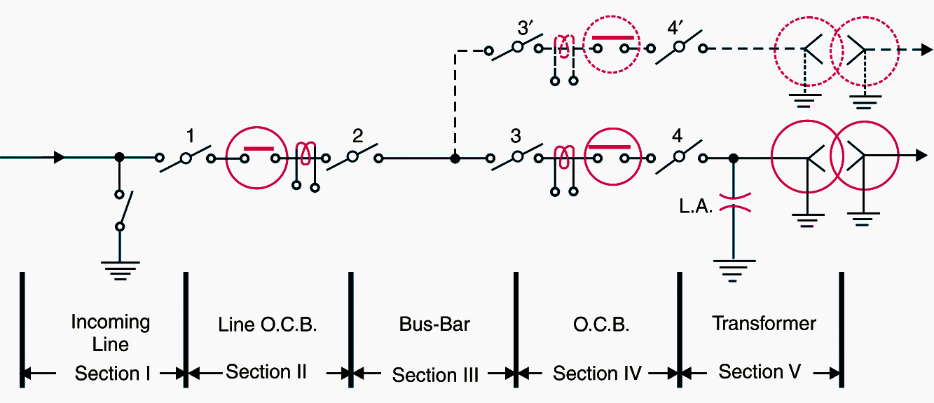

Figure 2 shows the use of isolators in a typical Substation. The entire Substation has been divided into V sections. Each section can be disconnected with the help of isolators for repair and maintenance.
For instance, if it is desired to repair section No. II, the procedure of disconnecting this section will be as follows. First of all, open the circuit breaker in this section and then open the isolators 1 and 2. This procedure will disconnect section II for repairs.
After the repair has been done, close the isolators 1 and 2 first and then the circuit breaker.
A practical working explanation how it works (VIDEO)
2.4 Circuit breaker
A circuit breaker is an equipment which can open or close a circuit under normal as well as fault conditions. It is so designed that it can be operated manually (or by remote control) under normal conditions and automatically under fault conditions.
There are several main types of high voltage circuit breakers in use nowadays. You should read about CB types in this technical article.
Please note that isolator cannot be used to open a circuit under normal conditions! It is because it has no provision to quench the are that is produced during opening operation. This is why the use of circuit breaker is essential!
For still higher voltages, air-blast, vacuum or SF, circuit breakers are used.
2.5 Power Transformers
Transformers are an essential component for power transmission and distribution. Their ratings originate from their area of application, their construction, the nominal power and the transformation ratio.
A power transformer is used in a substation to step-up or step-down the voltage. Except at the power station where a step-up transformer is used to step-up generation voltage to a high value (say 132 kV or 220 kV or more) for transmission of electric power, all the subsequent substations use step-down transformers to gradually reduce the voltage of electric supply and finally deliver it at utilization voltage.
The use of 3-phase transformer (instead of 3 single phase bank of transformers) permits two advantages.
Firstly, only one 3-phase load-tap changing mechanism can be used. Secondly, its installation is much simpler than the three single phase transformers. The power transformer is generally installed upon lengths of rails fixed on concrete slabs having foundations 1 to 1-5 m deep.
For ratings up to 10 MVA, naturally cooled, oil immersed transformers are used. For higher ratings, the transformers are generally air blast cooled.
2.6 Instrument transformers (ITs)
Power lines in substations operate at high voltages and carry current of thousands of amperes. Typical output levels of instrument transformers are 1-5 amperes and 115-120 volts for CTs and VTs, respectively.
Voltage transformers (VTs) and current transformers (CTs) are used to transform the power system level (called the primary system level) of voltage and currents to the level required for these applications (called secondary systems).
Depending on the requirements for those applications, the instrument transformer design and construction can be quite different. Generally, the metering ITs require high accuracy in the range of normal operating voltage and current.
Protection ITs require linearity in a wide range of voltages and currents. During a disturbance, such as system fault or overvoltage transients, the output of the IT is used by a protective relay to initiate an appropriate action (open or dose a breaker, reconfigure the system, etc.) to mitigate the disturbance and protect the rest of the power system.
Instrument transformers are the most common and economic way to detect a disturbance.
There are several classes of accuracy for instrument transformers defined by the IEEE, CSA, IEC, and ANSI standards.
There are two types of instrument transformers: Current transformers (CTs) and Potential (voltage) transformers (PTs or VTs).
2.6.1 Current transformer (CT)
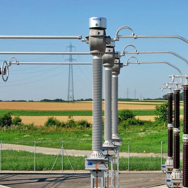
A current transformer in essentially a step-up transformer which steps down the current to a known ratio. The primary of this transformer consists of one or more turns of thick were connected in series with the line.
Suppose a current transformer rated at 100/5 A is connected in the line to measure current. If the current in the line is 100 A, then current in the secondary will be 5A.
Similarly, if current in the line is 50A, then secondary of CT will have a current of 2.5 A. Thus the CT under consideration will step down the line current by a factor of 20.

2.6.2 Voltage transformers (VTs)
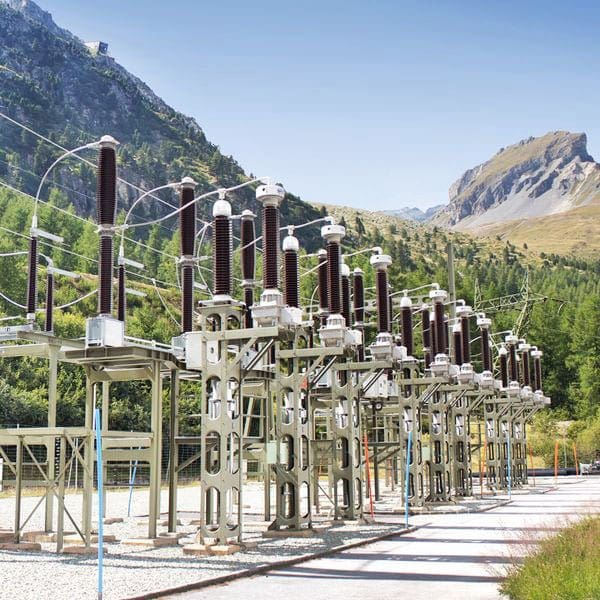
It is essentially a step down transformer and steps down the voltage to a known ratio. The primary of this transformer consists of a large number of turns of fine who connected across the line. The secondary winding consists of a few turns and provides for measuring instruments and relays a voltage which is a known fraction of the line voltage.
Suppose a potential transformer rated at 66kV/110V is connected to a power line. If line voltage is 66kV, then voltage across the secondary will be 110 V.

2.7 Protection relays
The function of protective relays in a substation is to cause the prompt removal from service of any element of a power system when it suffers a short circuit, or when it starts to operate in any abnormal manner that might cause damage or otherwise interfere with the effective operation of the rest of the system.
The relaying equipment is aided in this task by circuit breakers that are capable of disconnecting the faulty element when they are called upon to do so by the relaying equipment.
They must also withstand closing in on such a short circuit and then interrupting it according to certain prescribed standards.
Fusing is employed where protective relays and circuit breakers are not economically justifiable.

Although the principal function of protective relaying is to mitigate the effects of short circuits, other abnormal operating conditions arise that also require the services of protective relaying. This is particularly true of generators and motors.
A secondary function of protective relaying is to provide indication of the location and type of failure.
Such data not only assist in expediting repair but also, by comparison with human observation and automatic oscillograph records, they provide means for analyzing the effectiveness of the fault-prevention and mitigation features including the protective relaying itself.
Sensitivity, selectivity and speed
Sensitivity, selectivity and speed are terms commonly used to describe the functional characteristics of any protective relaying equipment. All of them are implied in the foregoing considerations of primary and back-up relaying.
Any relaying equipment must be sufficiently sensitive so that it will operate reliably, when required, under the actual condition that produces the least operating tendency.
How well any protective-relaying equipment fulfills each of these requirements must be known for each application.
The ultimate goal of protective relaying is to disconnect a faulty system element as quickly as possible. Sensitivity and selectivity are essential to assure that the proper circuit breakers will be tripped, but speed is the “pay-off.”
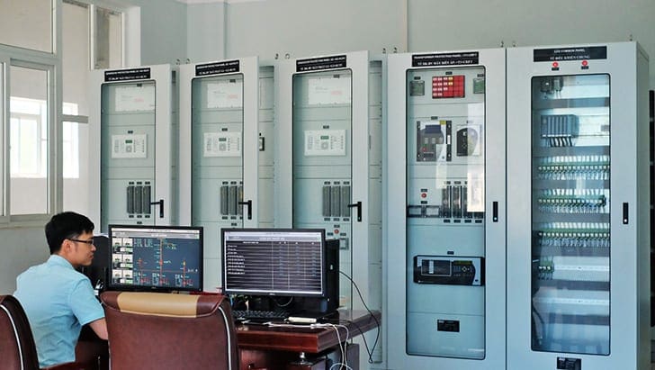
Control and relay protection panels
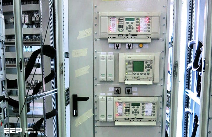
Most protection relaying, metering, and control equipment is usually located in control and relay panels installed within the control house in a substation.
There are many panel types is available to suit individual substation requirements.

2.8 Metering and indicating instruments
Every substation should have metering and indicating instruments (e.g. ammeters, voltmeters, energy meters etc.) installed in as substation to maintain observation over the circuit quantities.
2.9 Miscellaneous equipment
In addition to above, there may be following equipment in a power substation: fuses, carrier-current equipment, substation auxiliary supplies, batteries and other secondary equipment.
3. Busbar arrangements in substations
Busbars are the important components in a substation. There are several busbar arrangements that can be used in a substation. The choice of a particular arrangement depends upon various factors such as system voltage, position of substation, degree of reliability, cost etc.
The following are the important busbar arrangements used in substations:
3.1 Single busbar system
As the name suggests, it consists of a single busbar and all the incoming and outgoing lines are connected to it. The chief advantages of this type of arrangement are low initial cost, less maintenance and simple operation.
However, the principal disadvantage of single busbar system is that if repair is to be done on the busbar or a fault occurs on the bus, there is a complete interruption of the supply.
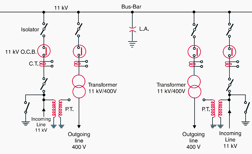
Figure 7 shows single busbar arrangement in a substation. There are two 11 kV incoming lines connected to the busbar through circuit breakers and isolators.
The two 400V outgoing lines are connected to the bus bars through transformers (11kV/400 V) and circuit breakers.

3.2 Single busbar system with sectionalisation
In this arrangement, the single busbar is divided into sections and load is equally distributed on all the sections. Any two sections of the busbar are connected by a circuit breaker and isolators.
Two principal advantages are claimed for this arrangement:
This arrangement is used for voltages up to 33 kV.
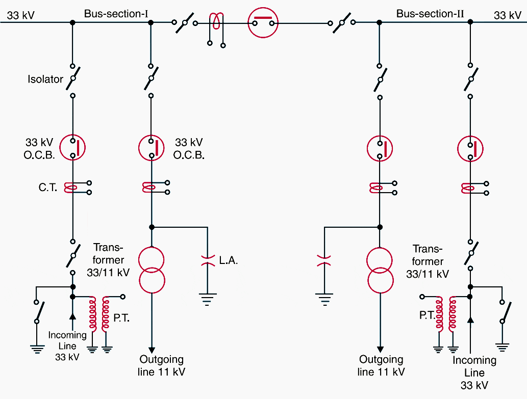
Figure 8 shows busbar with sectionalisation where the bus has been divided into two sections. There are two 33 kV incoming lines connected to sections I and II as shown through circuit breaker and isolators. Each 11 kV outgoing line is connected to one section through transformer (33/11 kV) and circuit breaker.
It is easy to see that each bus-section behaves as a separate busbar.

Double busbar system”>3.3 Double (or duplicated) busbar system
This system consists of two busbars, a “main” busbar and a “spare” busbar. Each busbar has the capacity to take up the entire substation load.
The incoming and outgoing lines can be connected to either busbar with the help of a busbar coupler which consists of a circuit breaker and isolators. Ordinarily, the incoming and outgoing lines remain connected to the main busbar.
For voltages exceeding 33kV, duplicate busbar system is frequently used.
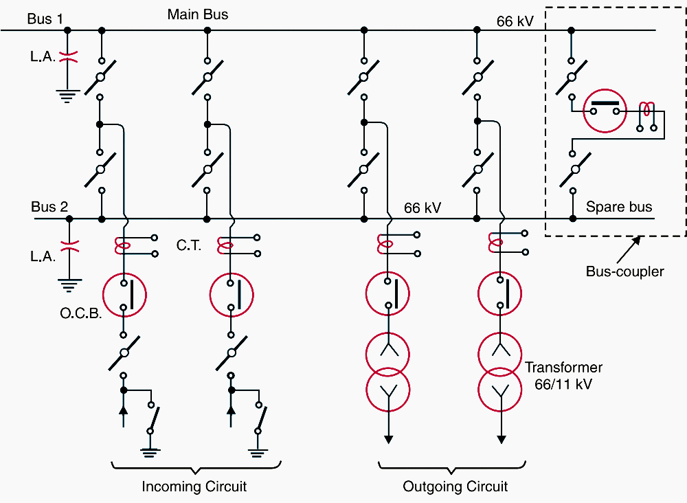
Figure 9 shows the arrrangement of duplicate busbar system in a typical substation.
The two 66kV incoming lines can be connected to either busbar by a busbar coupler. The two 11 kV outgoing lines are connected to the busbars through transformers (66/11 kV) and circuit breakers.

Sources:
- Elements of Power Systems by Pradip Kumar Sadhu and Soumya Das (Purchase hardcover from Amazon)
- Operation And Maintenance (O&M): Exterior Power Distribution Systems By Unified Facilities Criteria (UFC)
- A Capacitance Bridge for Determining the Ratio and Phase Angle of Potential Transformers – Bousman. H. W. and Ten Broeck, R. L.,
- The art and science of protective relaying – C. Russell Mason (GE)


Enough informatino for beginners with Videos. Keep it going. Thanks
Really liked your content. Not just the theory but also practical example. Great job. Keep it up. Thanks
Keep up the good work
I am an electrical engineer, I am involved in the management and operation of HV substations. The article is very useful for my work. Best regards!
Love your articles. Learning a lot Thank you.
The best ever website I always follow and learning from.thank you and be there everyday
i learned from the EEP message the shape of certaine equipements its work ie its electrical symbols. and it is very important to know the shape the job and if necessary all its different nomenclaure in generalin particulare, and its functionning with too much details.thank you.
Excelllent
Symbols used in this article don’t meet IEC standards.
To what standards do they meet?
I have enjoyed looking at your page.
Thanks,
Tim