
Estimated Study Time: 18 minutes
What are substations?
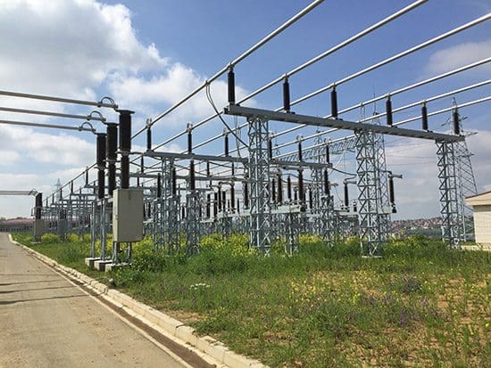
Substations are locations where transmission lines are tied together. They fulfill a number of functions. One of them is that they allow power from different generating stations to be fed into the main transmission corridors. Power substations also provide a terminus for interconnections with other systems and location where transformers can be connected to feed power into the subtransmission or distribution systems.
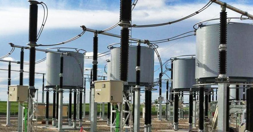
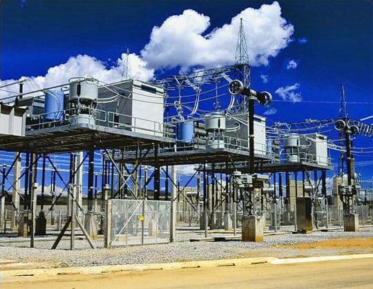
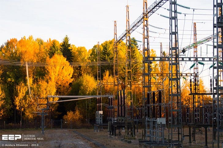 HV Substation Equipment For Engineers In a Nutshell (on photo: Substation in fall; photo credit: Anders Eliasson via Flickr)
They allow transmission lines to be segmented to provide a degree of redundancy in the transmission paths.
Substations provide a location:
- Where compensation devices such as shunt or series reactors or capacitors can be connected to the transmission system.
- Where transmission lines can be de-energized, either for maintenance or because of an electrical malfunction involving the line.
- For protection, control, and metering equipment.
Let’s see the contents of the following discussion:
- Common Substation Equipment:
- Other equipment you can see in substations:
Common Substation Equipment
There are a number of designs used for substations. However, there are elements common to all, so let’s see:
1. Bus
Bus is the given name given to the electrical structure to which all lines and transformers are connected. Buses are of two generic types: open air and enclosed.
Bus structures are designed to withstand the large mechanical forces that can result from fields produced by high short-circuit currents. These forces vary with the third power of the current. A bus section is the part of a bus to which a single line or transformer is connected.
2. Protective relays
Protective relays are devices that continuously monitor the voltages and currents associated with the line and its terminals to detect failures or malfunctions in the line/equipment.
Such failures are called faults and involve contact between phases or between one or more phases and ground. The relays actuate circuit breakers.
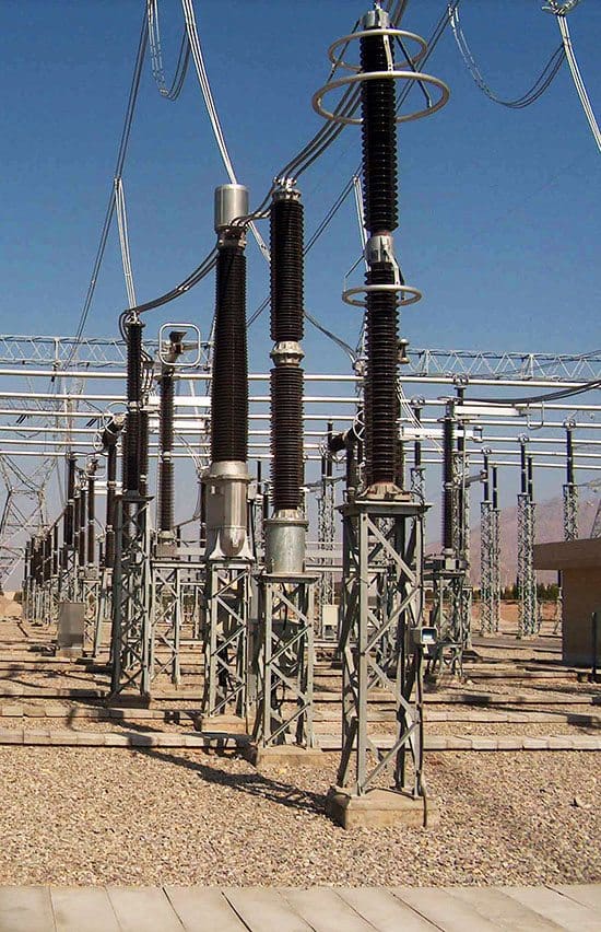
3. Circuit breakers
Circuit breakers are devices that are capable of interrupting the flow of electricity to isolate either a line or a transformer. They do so by opening the circuit and extinguishing the arc that forms using a variety of technologies such as oil, vacuum, air blast or sulfur hexafluoride (SF6).
Breakers may be in series with the line or transformer or may be installed on both sides of the bus section where the line connects.
They must be capable of interrupting the very high currents that occur during fault conditions and are rated by the amount of current they can interrupt. These fault current levels can be 20 or 30 times larger than the current flow under normal operating conditions, that is, thousands of amperes.
Circuit breakers also allow lines or transformers to be removed from service for maintenance. Circuit breakers normally interrupt all three phases simultaneously, although in certain special applications, single-phase circuit breakers can be employed, which will open only the phase with a problem.
To minimize the impact of electrical “shocks” to the transmission system, minimizing the total time for the relay to detect the condition and the circuit breaker to open the circuit is a critical design issue.
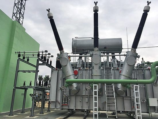
4. Transformers
Transformers are devices that are used to connect facilities operating at two different voltage levels. For example a transformer would be used to connect a 138kV bus to a 13kV bus.The transformer connects to all three phases of the bus. Physically the transformers can include all three phases within one tank or there can be three separate tanks, one per phase.
Larger capacity units may have three separate tanks because their size and weight may be a limiting factor because of transportation issues.
Transformers can be designed with two mechanisms to adjust the voltage ratio:
- One mechanism is the provision of more than one fixed tap position on one side of the transformer. For example, a transformer might have a nominal turns ratio of 345/138, with fixed taps on the 345kV winding of 327.8, 336.7, 345, 353.6 and 362.3.The transformer must be deenergized to adjust the fixed tap ratio.
- Another mechanism is called tap changing under load (TCUL). In this mechanism the ratio can be adjusted while the transformer is energized, providing greater operating flexibility. Some transformers have both types of mechanisms. With a fixed tap adjustment in the high voltage winding and the TCUL adjustment in the low voltage winding.
Another type transformer is an autotransformer, which is used when facilities at nearly the same voltage are to be connected, for example, 138kV to 115kV.
Rather than having two separate paths for the electricity, connected only by the magnetic flux through the transformer as in a conventional unit, the winding of autotransformer involves a tap on the higher voltage winding which supplies the lower voltage.
All larger transformers have mechanisms to remove the heat generated within the tank involving some manner of circulating the transformer insulating/cooling oil through an external heat exchanger involving fins mounted on the side of the transformer and fans to circulate air across the fins to maximize heat dissipation.
5. Disconnect switches
Disconnect switches are used to open a circuit when only “charging” current present is due. These would be used primarily to connect or disconnect circuit breakers or transformers which are not carrying load current.
They are also used in conjunction with circuit breakers to provide another level of safety for workers by inserting a second opening between station equipment out of service for work and the still energized section of line or bus.
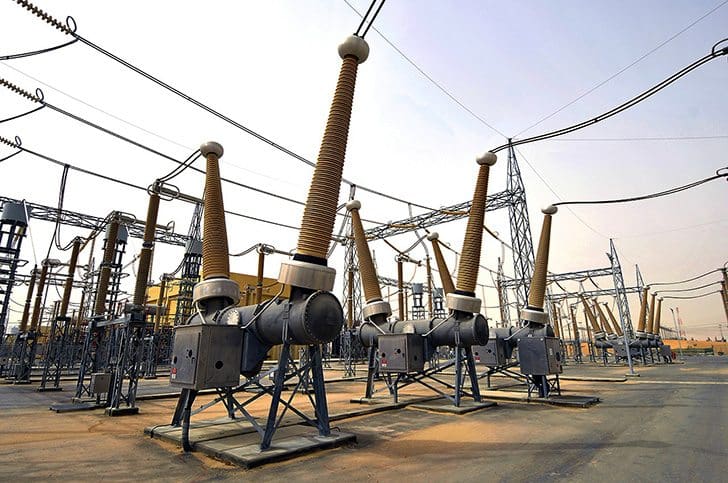
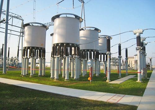
6. Lightning arrestors
Lightning arrestors are used to protect transformers and switchgear from the effects of high voltage due to lightning stroke or a switching operation.
They are designed to flashover when the voltage at the transformer exceeds a pre-selected level which is chosen by the station design engineers to coordinate with the basic insulation level of the transformer (BIL).
7. Metering equipment
Metering equipment is provided to measure line and transformer loadings and bus voltages so operating personnel can ensure that these facilities are within acceptable limits.
Metering equipment also is provided at some locations to measure the flow of energy for the billing that is required for sales and purchases of energy between various participants in the electric energy market.
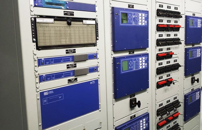
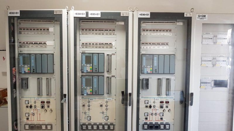
8. SCADA System
SCADA is an acronym for system control and data acquisition. It reflects the improvements in measurement, telecommunications and computing technologies that allow more and more automation of substation operation. Read more about SCADA systems here.
Other equipment you can see in substations
Depending on the electrical characteristics of a particular part of the transmission system, other equipment that may be located at a substation are:
1. Shunt reactors
Shunt reactors (reactors connected from the energized bus to ground) are installed to control high voltages that occur especially at night due to the capacitive effect of lightly loaded transmission lines. These reactors can be energized always or they can be energized only at specific times.
The windings, insulation and the external tank are similar to those used for transformers.
2. Series reactors
Series reactors are installed in a transmission line to increase the impedance of the line, to decrease current levels in the event of short circuits, or to reduce its loading under various operating conditions.
3. Shunt capacitors
Shunt capacitors are installed to provide mVArs to the system to help support voltage levels.
4. Series capacitors
Series capacitors are installed to reduce the effective impedance of a transmission line.
These would be installed in very long transmission lines to effectively reduce the electrical angle between the sending and the receiving parts of the system, enabling more power to flow over the line and increasing stability limits.
5. Phase angle regulating transformers
Phase angle regulating transformers are installed to control power flow through a transmission line, causing more or less power to flow over desired lines.
They use a variant on the design of a normal transformer, in which, due to the specialized way they are wound, they electrically inject an angular phase shift into the line. The angle can be made to either increase or decrease power flow on the line.
In recent years, some of them are being installed in overhead transmission lines to control parallel path flow, when power flows over paths in other systems not involved in transactions, or do not have adequate capacity.
6. FACTS (Flexible AC Transmission Systems)
FACTS (Flexible ac Transmission Systems) is a generic name used for a variety of devices intended to dynamically control voltage, impedance or phase angle of HVAC lines.
The development of such devices was first patented in 1975 by J.A. Casazza. The development of such devices was encouraged in the 1980s by a program of the Electric Power Research Institute (EPRI).
These devices mirror and extend the benefits of the fixed series and shunt inductors and capacitors previously discussed in that the FACTS devices allow rapid and precise adjustments.
Depending on the device, these FACTS devices provide a number of benefits:
- Increased power transfer capability,
- Rapid voltage control,
- Improved system stability, and
- Mitigation of sub-synchronous resonance
(a condition experienced in a number of regions in the United States, where oscillations occur caused by interaction of generator control systems and the capacitance of long transmission distances).
The following lists some of the devices:
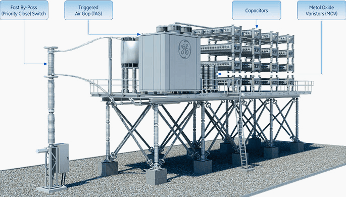
6.1. Static VAr Compensators (SVCs)
These devices employ fixed banks of capacitors, controlled with thyristors, which can switch them on and off rapidly. In many instances, there are also thyristor-switched inductors to prevent system resonance. Read more about SVCs here.
6.2. Thyristor Controlled Series Compensators (TCSC)
Thyristor Controlled Series Compensator (or Series Capacitor) (TCSC) is a thyristor controlled reactor is placed in parallel with a series capacitor, allowing a continuous and rapidly variable series compensation system.
6.3. Static Compensators (STATCOMs)
Static Compensators (STATCOMs) are gate turn-off type thyristors (GTO) based SVCs. They are solid-state synchronous voltage generators that consist of multi-pulsed, voltage sourced inverters connected in shunt with transmission lines.
They have the added advantage that their output is not seriously impacted by low system voltage.
Static Compensator – How it works (VIDEO)
6.4. Unified Power Flow Controllers (UPFC)
These devices have shunt connected STATCOM with an additional series branch in the transmission line supplied by the STATCOM’s dc circuit. These devices are comparable to phase shifting transformers.
They can control all three basic power transfer parameters: voltage, impedance and phase angle.
6.5. SVC Light (STATCOM)
Are based on voltage source converter technology equipped with Insulated Gate Bipolar Transistors (IGBT) a power switching component. They provide reactive power as well as absorption purely by means of electronic processing of voltage and current waveforms.
By the way, SVL Light is ABB brand name.
Reference // Understanding electric power systems – An overview of the technology and the marketplace by Jack Casazza Frank Delea (Purchase hardcopy from Amazon)
Related electrical guides & articles


Edvard Csanyi
Hi, I'm an electrical engineer, programmer and founder of EEP - Electrical Engineering Portal. I worked twelve years at Schneider Electric in the position of technical support for low- and medium-voltage projects and the design of busbar trunking systems.I'm highly specialized in the design of LV/MV switchgear and low-voltage, high-power busbar trunking (<6300A) in substations, commercial buildings and industry facilities. I'm also a professional in AutoCAD programming.
Profile: Edvard Csanyi

Excellent information for power system engineer
Thanks for the topics you have been putting up, sir. Really looking forward to learn more. Thumbs up👍
What’s the difference between a SVC substation and a switch yard.
VERY USEFUL FOR APPLICATION ENGINEERS IN ELECTRICAL T&D AND GENERATING PLANTS. LIKE TO HAVE SUCH PRACTICAL AUTHENTIC TECHNICAL AND CASE STUDIES PAPERS.
Thank you for the information, it is really good, your effort is appreciated.
thanks a lot. that is huge support
Well put together good info
Excelente y completa información