
Estimated Study Time: 20 minutes
HVDC transmission
This technical article examines in detail the main equipment of an HVDC converter station and discusses the layout of this equipment within the converter station. The interconnection of HVDC to the AC system is very complex, and nowadays are now forming an integral part of power transmission in the world today, a trend which will only increase.
 Figure 1 - Typical single line diagram of a bipole HVDC converter
The interconnection of HVDC can bring many benefits to the AC system.
Single line diagram of one end of a HVDC bipole converter
Figure 1 shows a typical single line diagram of one end of a bipole overhead transmission line HVDC converter station. The following discussion reviews the major components which make up the converter station.
- AC Switchyard
- AC Harmonic Filters
- High Frequency Filter
- Converter Transformer
- Converter
- DC Smoothing Reactor
- DC Filter
- DC Switchgear
- DC Transducers
1. AC Switchyard
The AC system connects to a HVDC converter station via a “converter bus”, which is simply the AC busbar to which the converter is connected.
Figure 1 shows a selection of AC connection arrangements that can be used in HVDC converter stations starting with a simple, single, 3-phase busbar with one switchable connection to the AC system and the switchable AC harmonic filters connected directly to it.

In such an arrangement it is not possible to use the AC harmonic filters for reactive power support of the AC system without having the converter energised (as the AC system connection is common).
Figure 2 shows a scheme comprising two converters and includes an additional circuit breaker dedicated to each converter. In this arrangement the AC harmonic filters can be used for AC reactive power support without energising the converter.

However, in common with Figure 1, a busbar fault will result in the complete outage of the converter station. to provide some additional redundancy a double busbar arrangement can be used as shown in Figure 3.
In Figure 3 an AC busbar outage will result in those loads connected to that busbar being disconnected until the disconnectors can be arranged to re-connect the load to the remaining, “healthy” busbar.

Disconnector rearrangement will typically take in the order of ten seconds to complete and in some circumstances such an outage may not be acceptable, hence the arrangement shown in Figure 4 can be used, where each load is connected via a dedicated circuit breaker to each busbar, allowing for fast disconnection and reconnection in the event of a loss of a busbar (typically around 300 ms).
A disadvantage of the arrangement shown in Figure 4 is the large number of AC circuit breakers required.

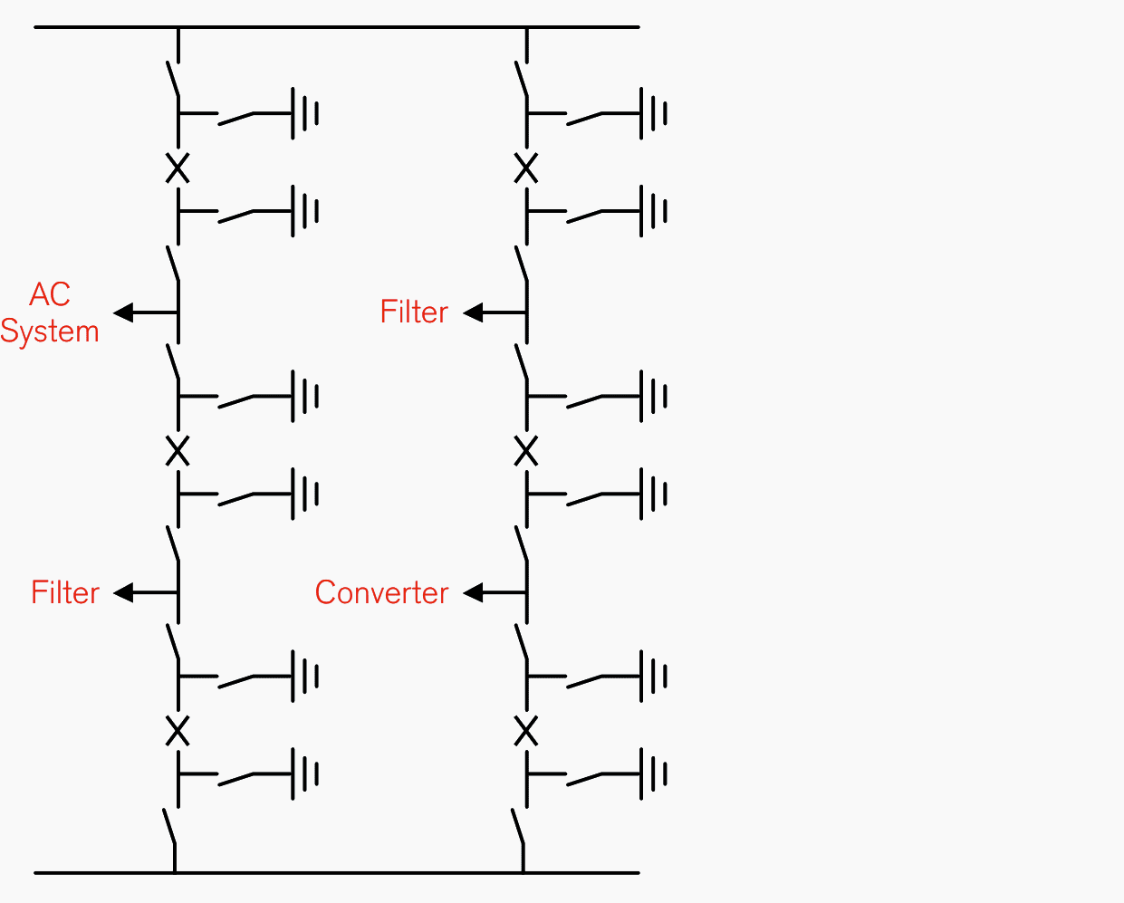
In order to reduce the number of circuit breakers, the arrangement shown in Figure 5 can be used. In Figure 5 two loads can be individually switched between two three-phase busbars via three circuit breakers, hence, this configuration is commonly known as a “breaker-and-a-half” arrangement.
Many other arrangements of AC switchyard configuration exist and have been used in association with existing HVDC schemes.
2. AC Harmonic Filters
Converter operation results in both the generation of AC current harmonics and the absorption of reactive power. In order to limit the impact of these AC harmonic currents and the absorbed reactive power, the converter station normally includes shunt connected switchable AC harmonic filters, either connected directly to the converter busbar or connected to a “filter busbar” which, in-turn, is connected to the converter busbar.
The AC harmonic filters are automatically switched-on and off with conventional AC circuit breakers when they are needed to meet harmonic performance and reactive power performance limits.

The AC harmonic filters are typically composed of a high voltage connected capacitor bank in series with a medium voltage circuit comprising air-cored air-insulated reactors, resistors and capacitor banks.
These components are selected to provide the required performance from the AC harmonic filter and to ensure that the filter is adequately rated.

3. High Frequency Filter
The converter operation will result in the generation of very high-frequency interference which will propagate out into the AC system from the converter bus. Whilst the magnitude and frequency of this interference is often of no importance to the safe operation of the AC system, there are some instances where this high-frequency interference may be undesirable, in particular when the AC system uses Power Line Carrier (PLC) signalling.
PLC signalling is a system which transmits a communication signal as an amplitude-modulated signal, superimposed on the fundamental frequency voltage signal of an AC power system.
As with the AC harmonic filter, the HF filter comprises a high voltage connected capacitor bank, an air-core air-insulated reactor and an additional low voltage circuit composed of capacitors, reactors and resistors which are referred to as a tuning pack.
Further reading:
4. Converter Transformer
The converter transformer is the interface between the AC system and the thyristor valves. Typically the HVDC converter transformer is subjected to a DC voltage insulation stress as well as the AC voltage stress normally experienced by a power transformer.
These AC and DC stresses are fundamentally different. The AC voltage stress is predominantly in the insulating oil and defined by the geometry and permittivity of the materials, whilst the DC stress is governed by the resistivity of the insulating materials which, in turn, vary with operating conditions.
Typically, the converter transformer is arranged as an earthed star-line winding and a floating-star and delta secondary windings. There is normally an on-load tap-changer on the line winding.
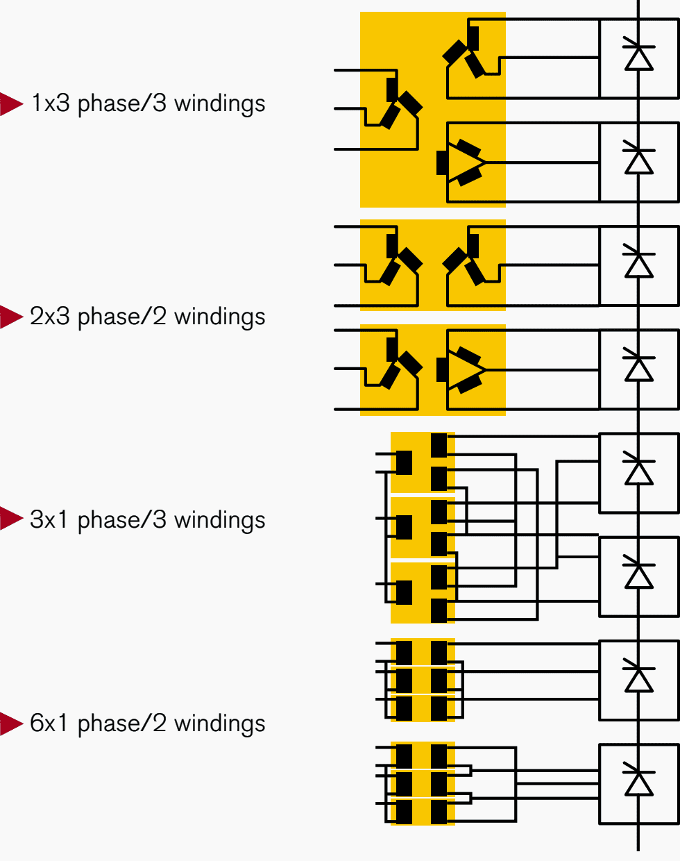
5. Converter
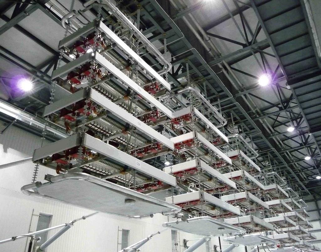
The converter provides the transformation from AC to DC or DC to AC as required. The basic building block of the converter is the six-pulse bridge. However, most HVDC converters are connected as twelve-pulse bridges. The twelve-pulse bridge is composed of 12 “valves” each of which may contain many series-connected thyristors in order to achieve the DC rating of the HVDC scheme.
For back-to-back schemes, where both the sending and receiving end of the HVDC link are located on the same site, it is typical for the valves associated with both ends of the link to be located within the same valve hall.
6. DC Smoothing Reactor
DC smoothing reactors are normally only required for power transmission schemes. For a HVDC transmission scheme, the DC smoothing reactor provides a number of functions but principally it is used to:
- Reduce the DC current ripple on the overhead transmission line or cable,
- Reduce the maximum potential fault current that could flow from the DC transmission circuit into a converter fault
- Modify the DC side resonances of the scheme to frequencies that are not multiples of the fundamental AC frequency
- Protect the thyristor valve from fast front transients originating on the DC transmission line (for example a lightning strike)
The DC smoothing reactor is normally a large air-cored air-insulated reactor and is principally located at the high voltage terminal of the HVDC converter for schemes rated at, or below, 500 kVDC.
Above 500 kV, the DC smoothing reactor is commonly split between the high voltage and neutral terminals.

7. DC Filter
Converter operation results in voltage harmonics being generated at the DC terminals of the converter, that is, there are sinusoidal AC harmonic components superimposed on the DC terminal voltage.
This AC harmonic component of voltage will result in AC harmonic current flow in the DC circuit and the field generated by this AC harmonic current flow can link with adjacent conductors, such as open-wire telecommunication systems, and induce harmonic current flow in these other circuits.
The DC filter is physically similar to an AC filter in that it is connected to the high voltage potential via a capacitor bank. Other capacitors along with reactors and resistors are then connected to the high voltage capacitor bank in order to provide the desired tuning and damping.
8. DC Switchgear
Switchgear on the DC side of the converter is typically limited to disconnectors and earth switches for scheme reconfiguration and safe maintenance operation. Interruption of fault events is done by the controlled action of the converter and therefore, with the exception of the NBS, does not require switchgear with current interruption capability.
Where more than one HVDC Pole share a common transmission conductor (typically the neutral) it is advantageous to be able to commutate the DC current between transmission paths without interrupting the DC power flow.
Figure 1 shows a typical Single Line Diagram (SLD) for a HVDC transmission scheme utilizing DC side switchgear to transfer the DC current between different paths whilst on load.
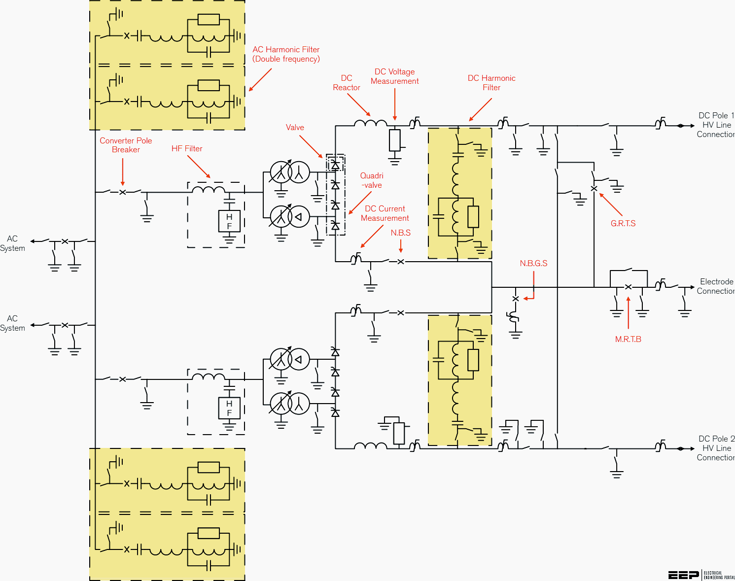
The following switches can be identified from Figure 1:
8.1 Neutral Bus Ground Switch (NBGS)
This switch is normally open but when closed it solidly connects the converter neutral to the station earth mat.
Operation with this switch can normally be maintained if the converter can be operated in a bipole mode with balanced currents between the poles, that is, the DC current to earth is very small. The switch is also able to open, commutating a small DC unbalance current out of the switch and into the DC circuit.
8.2 Neutral Bus Switch (NBS)
A NBS is in series with the neutral connection of each pole. In the event of an earth fault on one pole, that pole will be blocked. However, the pole remaining in service will continue to feed DC current into the fault via the common neutral connection.
The NBS is used to divert the DC current away from the blocked pole to ground.
8.3 Ground Return Transfer Switch (GRTS)
The connection between the HVDC conductor and the neutral point includes both a high voltage disconnector and a GRTS and is used as part of the switching operation to configure the HVDC scheme as either a ground return monopole or a metallic return monopole. The disconnector is maintained open if the HV conductor is energised in order to isolate the medium voltage GRTS from the high voltage.
The GRTS is closed, following the closing of the disconnector in order to put the HV conductor in parallel with the earth path.
8.4 Metallic Return Transfer Breaker (MRTB)
The MRTB is used in conjunction with the GRTS to commutate the DC load current between the earth (ground return) and a parallel, otherwise unused, HV conductor (metallic return).
The MRTB closes in order to put the low impedance earth return path in parallel with the metallic return path. The MRTB must also be able to open, causing current flowing through the earth return to commutate into the much higher impedance metallic return path.
9. DC Transducers
DC connected transducers fall into two types, those measuring the DC voltage of the scheme and those measuring the DC current.
DC voltage measurement is made by either a resistive DC voltage divider or an optical voltage divider. The resistive voltage divider comprises a series of connected resistors and a voltage measurement can be taken across a low voltage end resistor which will be proportional to the DC voltage applied across the whole resistive divider assembly.
Optical voltage transducers detect the strength of the electric field around a busbar with the use of Pockel cells ( voltage-controlled wave-plates, modulating the polarization of the light passing through)
DC current measurement for both control and protection requires an electronic processing system. Measurement can be achieved by generating a magnetic field within a measuring head which is sufficient to cancel the magnetic field around a busbar through the measuring head.
Optical current measurement makes use of, amongst others, the Faraday effect in which the phase of an optical signal in a fibre optic cable is influenced by the magnetic field of a busbar around which the cable is wound. By measuring the phase change between the generated signal and the signal reflected back from the busbar, the magnitude of the current can be found.
Sources:
- Alstom Grid
- Traveling Wave Fault Location on HVDC Lines by Alberto Becker Soeth Jr – GE Grid Solutions LLC, Brasil Paulo Renato Freire de Souza – GE Grid Solutions LLC, Brasil Diogo Totti Custódio – Interligação Elétrica do Madeira S.A, Brazil and Ilia Voloh – GE Grid Solutions LLC, Canada
Related electrical guides & articles


Edvard Csanyi
Hi, I'm an electrical engineer, programmer and founder of EEP - Electrical Engineering Portal. I worked twelve years at Schneider Electric in the position of technical support for low- and medium-voltage projects and the design of busbar trunking systems.I'm highly specialized in the design of LV/MV switchgear and low-voltage, high-power busbar trunking (<6300A) in substations, commercial buildings and industry facilities. I'm also a professional in AutoCAD programming.
Profile: Edvard Csanyi

I’m very happy to read all this because, I didn’t saw all this before!
Thanks ❤
Regards :- 🇮🇳🇮🇳🇮🇳
I’m very proud with EEP Electrical Engineering and I like to know everything
Very Comprehensive and Explained in simple yet effective covering the Basics of the HVDC System.
Very good 👍