
Estimated Study Time: 20 minutes
Hydropower Energy
Nowadays, when we all see and feel the colossal crisis looming on the horizon, the question of energy security is among the first things on the table in each country’s management. It’s now essential more than ever for each country to use all its energy resources wisely. This is where we come to one of my favourite topics (for a reason) – Hydroelectricity.
 Electrical engineering for hydropower, from run-of-river to pumped storage plants
Hydropower plants (HPPs) are the critical elements in every power system. This technical article discusses the essential electrical engineering for hydropower, from run-of-river to pumped storage plants (PSPs).
- Basics of hydropower plants
- Hydro generators, speed/polarity and mounting types
- Motors/Generators, new opportunities for pumped storage schemes
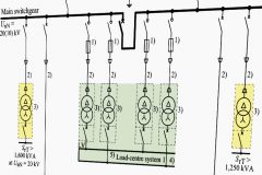
- Balance of plant, transmission and distribution challenges (AIS, GIS, transformers, schematics, etc.)
1. Basics of Hydropower plants
Hydroelectricity is the oldest yet in many terms the most efficient renewable energy source. Prime mover uses a combination of potential power of water column H or head [m] and discharge flow Q [m3/h] to develop mechanical power that will keep generator rotor running and producing electricity at stator leads thanks to electromagnetic induction.
There is indeed a direct correlation with these parameters and active power available at dispatchment point, being:
𝑃 ≈ 9,81 × 𝑄 × 𝐻 × 𝜂 [W]
where η is efficiency of all components (turbine, alternator and transformer).
This contributes to a relative reduction of generator polarity and allows a gearless solution that is however far different from the direct coupling of large gas turbines where the rotating speed is usually 3000/3600rpm.
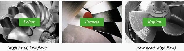
Figure 1 – Pelton (impulse type), Francis and Kaplan (reactive type) turbine runner
While prime mover speed is in fact directly linked with turbine geometry, water head and flow, generators above a certain rating shall operate at synchronous speed with electrical grid, being either 50Hz or 60Hz. Small hydro plants, especially low head recovery solutions below 500kVA will use induction generators or permanent magnet generators (PMG) that are exceptions to this rule.
Speed multiplier gearboxes are rarely used for large units, at contrary the pole/frequency equation is exploited:
n = 60 × f / 2Np [rpm]
where f is grid frequency in [Hz] and Np is number of poles and n is rotor speed in [rpm].
Pelton units have indeed a dedicated mechanical component (diverter plate) to prevent this risk that can lead to catastrophic consequences since although absolute speed is definitely lower than turbogenerators, considering rotor inertia and fact that contrary to gas turbines (and partly to steam turbines) you cannot simply cut-off turbine fuel and damper the speed overshoot only.
Table 1 – Turbogenerator classification in regards to the poles number and rotation speed
| Poles | Rotation Speed (rpm) | Type | |
| 50 Hz | 60 Hz | ||
| 2 | 3000 | 3600 | Turbo |
| 4 | 1500 | 1800 | |
| 6 | 1000 | 1200 | Fast Hydro |
| 8 | 750 | 900 | |
| 10 | 600 | 720 | |
| 12 | 500 | 600 | |
| 14 | 429 | 514 | |
| 16 | 375 | 450 | |
| 18 | 333 | 400 | |
| 20 | 300 | 360 | Slow Hydro |
| 40 | 150 | 180 | |
Finally, although this has no impact on rotating equipment per se, plant electrical balance of plant and operation philosophy will be impacted by hydro plant type either a run of the river installation with minor civil works (and possibly even off grid) or a conventional scheme involving an upstream dam or even a pumped storage scheme with two reservoirs / dams.
Go back to the Contents Table ↑
2. Hydro generators, speed/polarity and mounting types
Hydro generators differs significantly from turbounits in terms of rotor geometry, while a four pole generator is the standard for industrial power generation or six poles motors are used only in mills or wherever an high efficiency and torque at low speed is needed, even the fastest Pelton runners will most probably require an higher polarity.
As a note the absolute speed of the prime mover shall not be confused with the characteristic hydro turbine speed (or Nq) that counterintuitively is very high for very slow runners, e.g. Kaplan units.
Airgap between stator and rotor will significatively different for high polarity hydro generators, having in fact almost a linear gap that will impact the electromagnetic design and generator equivalent circuit.
Figure 2 – Typical pole pitch & airgap for hydro generators

In particular the quadrature axis components of reactances will be affected, alongside some constructive details e.g. magnetic sheet grain orientation, at least for small units since for medium and large equipment cost considerations will always favor the non-oriented grain silicon steel material.
Related electrical guides & articles


Marco Bruschini
Chartered engineer with +10y of experience in electrical rotating and static equipment engineering procurement and installation, for renewables (hydroelectric) and natural gas plants. industrial and O&G markets (onshore and offshore). Genuine interest for energy transition and electrification, with a focus on integration of new energy sources in national grid and digitalization of control system and plant automation, including remote diagnostic.Profile: Marco Bruschini
