Polarity Detection
This is needed for identifying the primary and secondary phasor polarities. It is a must for poly phase connections. Both a.c. and d.c methods can be used for detecting the polarities of the induced emfs.

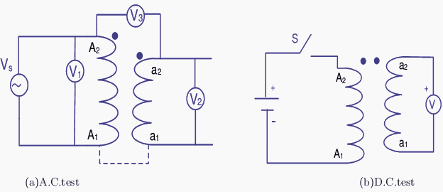
The transformer is connected to a low voltage a.c. source with the connections made as shown in the Figure 1 (a). A supply voltage Vs is applied to the primary and the readings of the voltmeters V1, V2 and V3 are noted. V1 : V2 gives the turns ratio.
If V3 reads V1−V2 then assumed dot locations are correct (for the connection shown).

The beginning and end of the primary and secondary may then be marked by A1 − A2 and a1 − a2 respectively. If the voltage rises from A1 to A2 in the primary, at any instant it does so from a1 to a2 in the secondary.
If more secondary terminals are present due to taps taken from the windings they can be labeled as a3, a4, a5, a6. It is the voltage rising from smaller number towards larger ones in each winding. The same thing holds good if more secondaries are present.
Figure 1 (b) shows the d.c. method of testing the polarity. When the switch S is closed if the secondary voltage shows a positive reading, with a moving coil meter, the assumed polarity is correct. If the meter kicks back the assumed polarity is wrong.
Reference: Electrical Machines I – Prof. Krishna Vasudevan, Prof. G. Sridhara Rao, Prof. P. Sasidhara Rao


hi ,, I noted the concepts of polarity check but I want to conform that primary and secondary inductance difference with different polarity
how much dc should be applied?
completed IR test , then doing polarity the galvanometer deflection is not showing . But before IR , galvanometer defelection is correctly showed. . Whats the reason……?
Hi, i’ve got one problem bro. Just help me out of it. Jut charged one 33 KV board first time and found problem with line vt 33KV/110V. B phase VT secondary wire burnt from VT terminal to the start point TB. Secondary circuit MCB didnt tripped and relay showed unbalanced voltages.
Is line VT is dead ???? or there is problem with Star point wiring???
Suspected Does VT polarity of B phase VT secondary wires reversed may cause these problem???
Good for learning my student
Hanza Yunus,
In the DC circuit when the switch closes to make the circuit the DC voltage across the winding changes from 0 to full battery voltage. This step change that occurs for only a few milliseconds is in fact an ac voltage (small change in voltage over small time period). Therefore we see this induced voltage lasting on the secondary (induced ac voltage lasting a few msec has a DC average that is picked up with DC meter). It is called a flicker test because you will only get DC voltage flick from 0V to the induced voltage very quickly before returning back to 0. If this induced voltage is positive then the polarity is shown as per the diagram and if its negative then the polarity is opposite (reverse polarity)
Its work to me using battery even on big transfo….to find the polarity of the transfo…
Umm.. if you apply a DC voltage to the primary it will put a charge on the secondary side.. this is basic electronics people…. just because it is constant 25kv doesnt mean it wont induce a voltage on the opposite side…. the difference here is that DC will use the Peak Voltage and A/C will use an RMS Value because with the cycles you loose that peak….
Do you not remember putting 12vDC on a coil then letting your buddy hold the ends of the coil to get that inrush shock when you remove the current?!? So fun in school….
to author,
i m a bit confused here, if one energizes the primary of a T/F with DC voltage, due to constant flux, emf should not b induced in the secondary. how come can we get deflection in mechanical voltmeter ?
would you mind elaborating a bit, huh ?
A Dc supply applying to primary of transformer the winding is damaged,how can apply the dc supply for polarity test
i think it is a pulse not continous dc supply
i think it is better for knowing the polarity to use DC method but use ammeter not voltmeter
, please i want more article to show how to design polarities of the CT
haa. if you apply a DC voltage to the primary it will put a charge on the secondary side.. this is basic electronics people…. just because it is constant 25kv doesnt mean it wont induce a voltage on the opposite side…. the difference here is that DC will use the Peak Voltage and A/C will use an RMS Value because with the cycles you loose that peak….
Do you not remember putting 12vDC on a coil then letting your buddy hold the ends of the coil to get that inrush shock when you remove the current?!? So fun in school…