Introduction to IEC 61850
Since IEC 61850 was published as an international standard for communication in substations, the standard has found broad acceptance on the markets. In the first substations to use it, the primary aim was successful implementation of existing concepts and solutions using the new technology.
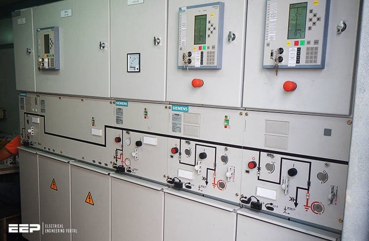
This positive experience from the initial projects secured the trust of the substation operators. However, these substations did not yet make use of the potential of IEC 61850.
With the rapidly growing number of implemented substations, confidence grew in the equipment and the first applications arose that made specific use of the new technology.
The most frequent control application was the decentralization of switchgear interlocking using GOOSE messages.
In addition, IEC 61850 offers the possibility of replacing parallel wiring with Ethernet and of implementing fast information exchange between devices. This article chiefly deals with this aspect and contrasts these concepts with the conventional approach.
Two practically proven examples demonstrate how modern solutions for digital substation automation incorporating new functions from IEC 61850 increase the benefit for users.
1. Distributed synchro-check
The synchro-check function checks before closure of a circuit-breaker whether the electrical parameters of the two subnetworks are within the defined limits.
This check is necessary to limit transient phenomena on connection. For this purpose, the voltage of the feeder to be switched is compared with the busbar voltage for magnitude and phase angle, and frequency values.
This ring line distributes the voltage to all bays and the BCU in the feeder to be switched picks off the voltage from the ring line. Now, all necessary information is available and the BCU autonomously checks whether the synchro-check conditions are fulfilled.
If the voltage amplitude, angle, and frequency differences are within the defined limit values, release is performed by the synchro-check function and the circuit-breaker closes.
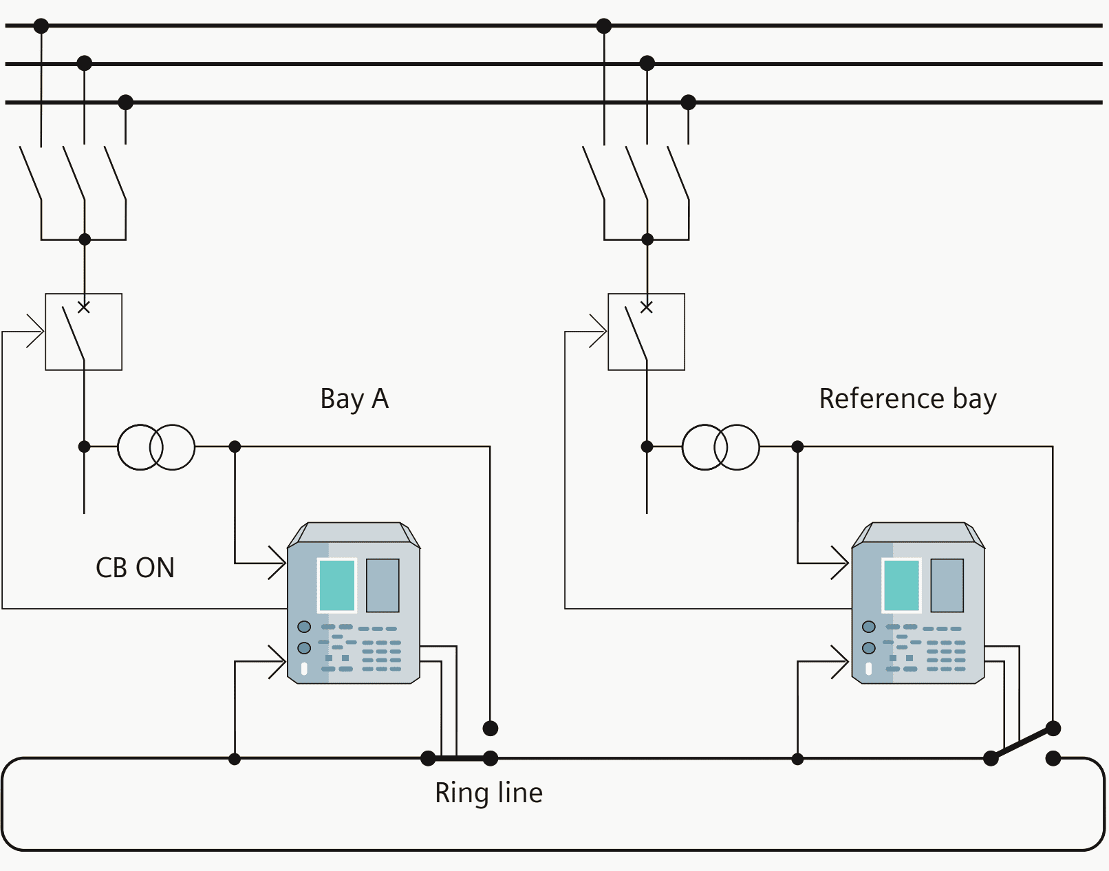

1.1 Conventional concept
Implementation of the distributed synchrocheck function with digital control technology has been state of the art for many years.
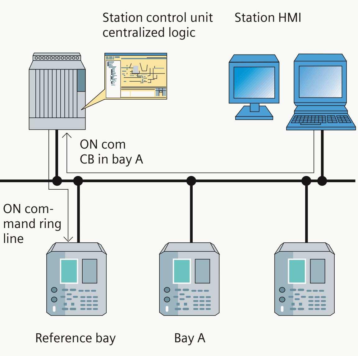
In most substations with this functionality, the logic for determining the reference bay is implemented centrally in the station control unit.
This means the control at station level issues a command to close the circuit-breaker of a bay A. This command is received in the station control unit and the reference bay is selected in centralized logic that takes account of the relevant position indications and information items. Then the station control unit sends a command to the selected BCU in the reference bay to close the ring line relay.
The BCU of bay A can then run the synchrocheck.

1.2 Concept using peer-to-peer communication
Since the introduction of IEC 61850, a new communication service has been available for efficient distribution of information between devices of the bay level.
The application described here shows how the GOOSE (generic object-oriented substation event) mechanism can be used to advantage.
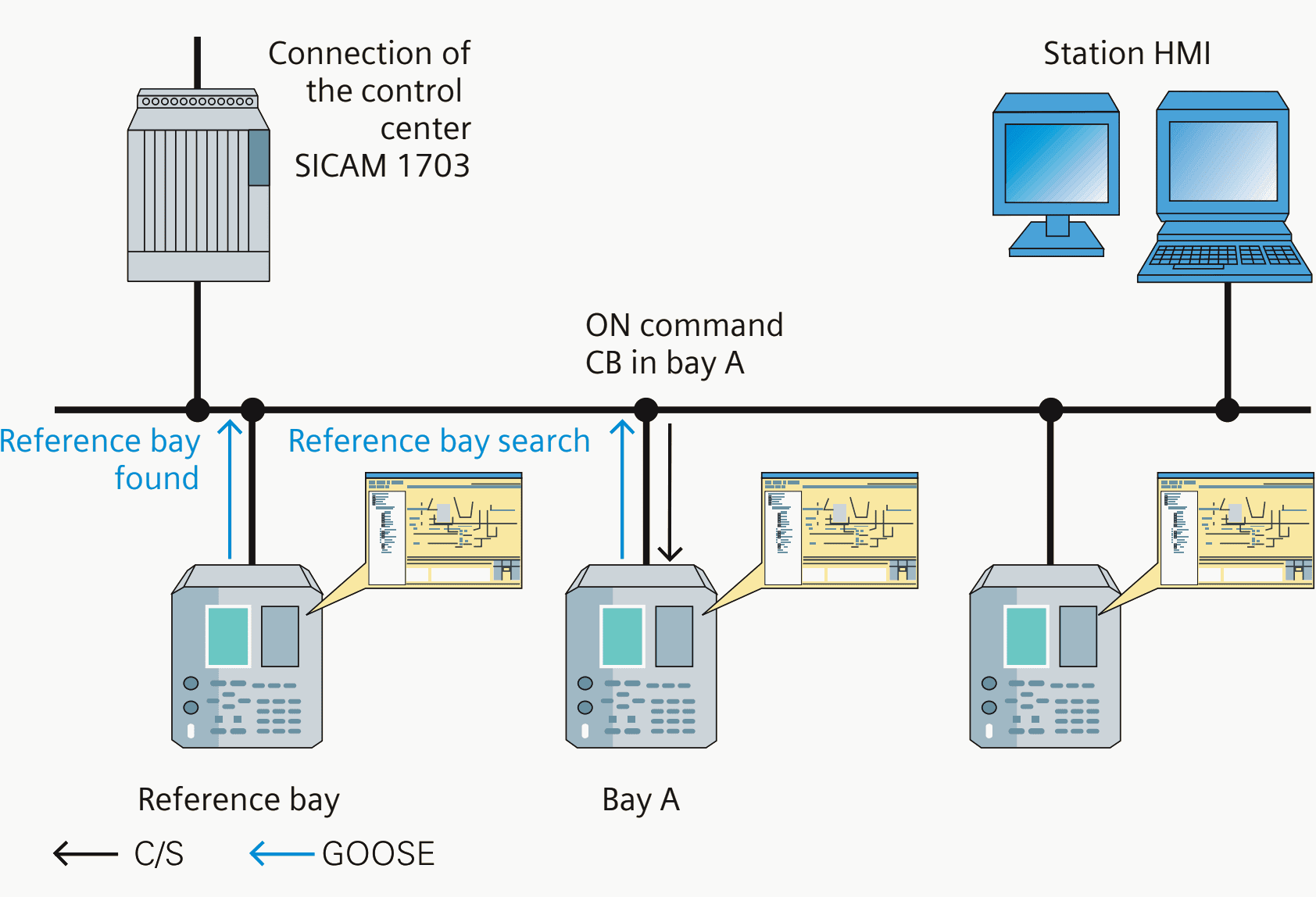
As in the conventional concept, the logic considers the position indications and additional information items in determining whether each feeder can be used as the reference bay. The non-bay-specific data that is required for selection is also exchanged among the BCUs in GOOSE messages.
In typical substations, several bays are usually suitable for use as reference bays. A single reference bay is selected by taking into account a previously defined sequence in the local logic. The BCU that is located in a reference bay due to the topology information and is at the head of the sequence sends the “Reference bay found” message to all other BCUs in a GOOSE telegram and connects the voltage via the ring line relay.
The ensuing test of the synchro-check conditions in the BCU of bay A and release of the control command is performed in the same way as in the conventional concept.

1.3 Benefit of the solution
Migrating the logic function from the BCU to the bay level improves the availability of the solution. Depending on the level of system availability required, redundant implementation of the station control unit can be dispensed with.
2. Mesh station automatic switching
A mesh station is a type of primary substation configuration that is economical in its use of circuit-breakers.
Although there are many variants, the typical configurations are single switch and four switch meshes, the names inferring the number of circuit-breakers used to accomplish the layout.
A mesh corner would typically have a feeder and up to two transformers connected – this means with four circuit-breakers, a station could be built with 4 feeder and 8 transformer circuits.
If a circuit-breaker requires maintenance, it may be taken out of the mesh without any loss of supply.
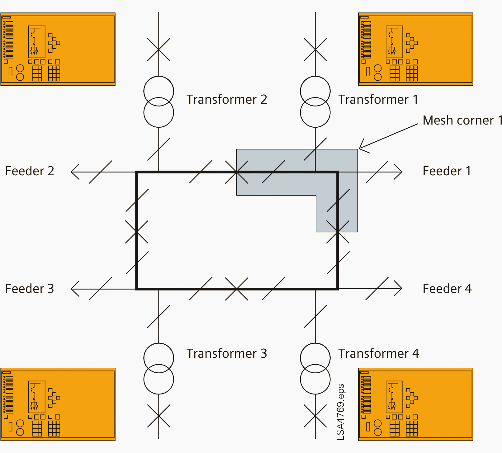

2.1 Mesh station automatic switching
Following a trip event for the mesh to ‘selfheal’, an automatic switching and delayed automatic reclose (DAR) system is required.
For example, for a feeder fault, all circuit-breakers connected to the feeder’s mesh corner must trip, including any transformer low-voltage circuit-breakers and remote substation circuit-breakers through intertrip signalling.
If the first circuit-breaker to automatically close trips then the feeder is deemed to have a persistent fault and the mesh DAR system opens the feeder disconnector at both ends of the circuit – after the feeder has been removed from the mesh corners, the mesh circuit-breakers commence automatic reclosure.
For transformer faults, once circuit-breakers have tripped, the transformer is automatically isolated by opening its disconnector before the mesh circuit-breakers reclose in their sequence.
2.2 The solution
A solution with one BCU per mesh corner was developed. This gave the benefits of reduction of installation costs and using a future proof industry standard rather than a bespoke solution.
The automatic switching and delayed automatic reclosure functions were developed using a graphical logic tool which was used to diagnose the bay control units. A test system shows a single line diagram of the substation from which switchgear positions can be manually changed, analog values controlled and protection events signaled.
The visualization interfaces to PROFIBUS input/output devices which are in turn connected to the bay control units being tested. The test system responds to events, i.e. simulates disconnector opening/closing and allows test sequences to be easily created and replayed for repeatable testing.
Using this test system, the specific functioning of the delayed automatic reclose (DAR) function can easily be verified in the BCUs and there is no further obstacle to successful commissioning of the substation.
Summary
The examples discussed show that IEC 61850 offers a wide range of application possibilities exceeding by far current applications.
A thorough analysis will reveal the advantages of IEC applications. However, it is for the operator of the substation and its supplier to decide on the degree to which alterations of existing concepts and systems should be made.
Reference // Efficient Energy Automation with the IEC 61850 Standard Application Examples by Siemens




Power electronics & transmission and distribution it’s details
Good morning
the benefit and purpose of the connection tray in the grounding japer. thank you
Me very like papers this…
Interested to be a member. How?
Hi Rodelio, feel free to find more information about our Premium Membership here:
https://electrical-engineering-portal.com/premium-membership-2