
Estimated Study Time: 16 minutes
From RTUs to IEDs…
Intelligent electronic devices (IEDs) have been deployed extensively in power automation systems recently, and the shift from RTUs to IEDs is evident due to the integration and interoperability features of the IEDs. This technical article briefly explains the IED advanced functionality to present a holistic view of automation in power systems.
 IED (Intelligent Electronic Device) advanced functions that make our life better
The IED brings a relay panel with many single-function electromechanical relays, control switches, extensive wiring, and much more into a single box.
In addition the IED handles additional features like self and external circuit monitoring, real-time synchronization of the event monitoring, local and substation data access, programmable logic controller functionality, and an entire range of software tools for commissioning, testing, event reporting, and fault analysis.
1. The role of IEDs in power systems
IEDs are devices that can be connected to a LAN and communicate with other devices over the LAN and have processing capabilities. A large number of IEDs are available currently, relay IEDs being the most commonly used for automation purposes. However, the smart meter used for home automation is an IED and so is a programmable logic controller (PLC) used for automation.
Thus IEDs have become the basic building blocks for automation of power systems. However, it is not easy to replace all the existing RTU and related equipment with IEDs, and different approaches are used to integrate the legacy systems with the new systems.

2. IED advanced functions
2.1 Protection function including phasor estimation
The protection function is the primary function of a relay IED, as IEDs are primarily the improvement on the microprocessor-based relays. There are tremendous improvements in the new IEDs as more accurate measurement principles and less auxiliary equipment are required.
Auxiliary CTs can be eliminated in a transformer differential relay, as the new relay has a CT mismatch correction function, as the original primary transformer currents are available for further analysis in a modern relay IED.
Similarly, with appropriate techniques, and numerical comparison algorithms, the CT mismatch, inrush, and CT saturation problems can be solved without external devices.
With the generalized numerical relay (Figure 2) and with the amount of information commonly available, it is possible to recreate the majority of modern digital and numerical relay equipment.

The following data-processing modules constitute the generalized numerical relay:
1. Isolation and analog signal scaling
Current and voltage waveforms from instrument transformers are acquired and scaled down to convenient voltage levels for use in the digital and numerical relays.
2. Analog anti-aliasing filtering
Low-pass filters are used to avoid the phenomenon of aliasing in which the high-frequency components of the inputs appear to be parts of the fundamental frequency components.
3. Analog-to-digital conversion
Because digital processors can process numerical or logical data only, the waveforms of inputs must be sampled at discrete times.
To achieve this, each analog signal is passed through a sample- and-hold module, and conveyed, one at a time, to an analog-to-digital converter (ADC) by a multiplexer.
4. Phasor estimation algorithm
A software algorithm implemented in a microprocessor estimates the amplitude and phase of the waveforms provided to the relay. This is of great importance in modern monitoring systems, as phasor measurements are becoming an integral part of the system monitoring.
5. Relay algorithm and trip logic
The equations and parameters specific to the protection algorithm and the associated trip logic are implemented in the software of the microprocessor used in the relay.
The microprocessor calculates the phasors representing the inputs, acquires the status of the switches, performs protective relay calculations, and finally provides outputs for controlling the circuit breakers.
The processor may also support communications, self-testing, target display, time clocks, and other tasks.
2.2 Programmable logic and breaker control
A modern relay IED eliminates the use of external programmable logic controllers (PLCs) as the IED can handle logical inputs and outputs of the protection functions, which can be connected to flip flops and/or gates of the IED directly.
Figure 2.12 presents an example of programmable logic tools. In Figure 2.13, an example of a PC-configuration tool for user programmable logic is shown.
Example of Logic Editor (VIDEO)
This tutorial explains the interlocking of controll commands in SIPROTEC 5 using the logic editor “CFC”.
Programming relay in AcSELerator QuickSet (VIDEO)
This video explains how to program SEL protection relay in AcSELerator QuickSet.
2.3 Metering and power quality analysis
Metering capabilities of the IEDs became acceptable to the power utilities quickly, and major cost saving was achieved by combining the non-revenue metering function into the IEDs.
It may be noted that the primary CTs and VTs for protection purposes may not be accurate enough for normal current measurement for revenue metering. The normal metering functions include measuring the voltage and current root mean square (RMS) values and the real and reactive power.
Load profiling is another metering activity that can be achieved using IEDs where the power factor profile, ampere demand, long-term RMS voltage value, and so on, can be monitored and can be used for load profiling for long-term expansion planning.
Using the PLC and metering functions, many system requirements can be met without additional effort, like capacitor bank control by the reactive power data monitoring and control algorithm implemented using a PLC and programmable output contacts.

Figure 3 shows the connection to a protection-class and instrument current transformer for a feeder. The necessary protection functions are assigned to the protection-class current transformer and the measurement functions are assigned to the instrument transformer according to the application.
The highly precise measured values and status information provided by the protection relays can be transmitted over the high-performance communication system to automation systems such as a substation and power systems control or central analysis systems.
2.4 Self-monitoring and external circuit monitoring
IEDs have card-level diagnostic capabilities for internal problems, with a self-monitoring software, which can detect up to 98% of the problems, such as hardware failure, memory failure, and power supply problems.
Interface monitoring includes checking the inputs to the IEDs and can be verified by simple methods. For example, the input currents to the relay from the three phases should add up to three times the neutral current if any. If there is any deviation, the analog channel of any of the currents could be faulty. The relay can block the false tripping.
External circuit monitoring will include monitoring of the circuit breaker coil for any interruption in the trip-close path and can also indicate an instrument transformer failure.
Modern protection relays are equipped with many monitoring procedures. These detect faults, internal as well as external, in secondary circuits, store them in logs, and report them. This information is used to record the device fault and helps to determine the cause of the error in order to take appropriate corrective actions.
2.5 Event reporting and fault diagnosis
Relay IEDs eliminate the digital fault recorders because waveform recording during a fault can be performed by the IEDs, whereas the electromechanical relays did not have such capability. Event reporting can be easily done by relay IEDs eliminating sequence of events (SOE) recorders.
The relay IEDs save the captured data in nonvolatile memory and disturbance event reports (pick up, trip, and auto-reclose), and general event reports like changes of settings have to be saved and managed separately.
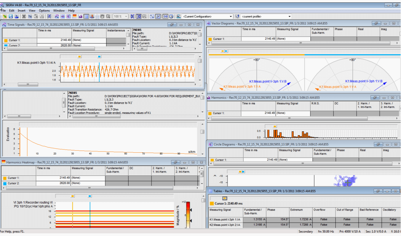
Time stamping of all events is done by the IEDs, and GPS synchronization for this purpose and a battery backup for the real-time clock are essential. The events, once time tagged correctly, can be reported in the correct sequence in which they occurred, eliminating further sequencing at the control room.
It is hence easy to perform fault diagnosis after a fault, as the values will be saved in the IED and can be retrieved later, even in case of a blackout.
Event analysis of SEL protection relay (VIDEO)
Learn how to perform Event Analysis using an SEL-751 feeder protection relay.
Protection relay setting and disturbance record (VIDEO)
2.6 Tools for settings, commissioning, and testing
User-friendly software tools are key to better planning, programming, commissioning, and testing of an IED. The elaborate avenues and application functionalities of an IED can be handled only by an intuitive, easy-touse PC program.
Almost every IED come with menu-driven intuitive, easy-to-use, flexible software programming tools for settings and configurations during commissioning.
These user-friendly programs come with factory presettings that simplify the job of the commissioning personnel.
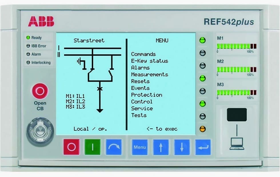
2.7 Programmable LCD display
The programmable LCD display is a great tool in the new generation of IEDs. This is used for graphical information as well displaying text and can be switched between graphic and text modes.
Figure 6 shows the display of relay IEDs. The topology of the bus and breaker including isolators, disconnecting switches, and many more configurations can be programmed using the software tools in the graphic mode. Text mode of the LCD display is used for settings and detailed display of the metering values in primary or secondary units.
The LCD display can be switched between text and graphics modes.
References //
- Power System Scada and Smart Grids by Mini S. Thomas and John D. McDonald (Purchase hardcopy from Amazon)
- Pоwеr Ѕyѕtеm аnd Mоdеlling Rеlаyѕ: Еxplоrаtоry Ѕtudy By Ibrahim Elnoshokaty
- Distribution Automation Handbook by ABB
- Automated Fault and Disturbance Analysis: Understanding the Configuration Challenge by M. Kezunovic, Fellow, IEEE, S. Sternfeld, M. Datta-Barua, Member, IEEE, D. Maragal, Member, IEEE, and T. Popovic, Senior Member, IEEE
Edvard Csanyi
Hi, I'm an electrical engineer, programmer and founder of EEP - Electrical Engineering Portal. I worked twelve years at Schneider Electric in the position of technical support for low- and medium-voltage projects and the design of busbar trunking systems.I'm highly specialized in the design of LV/MV switchgear and low-voltage, high-power busbar trunking (<6300A) in substations, commercial buildings and industry facilities. I'm also a professional in AutoCAD programming.
Profile: Edvard Csanyi

intelligent electronic device programmer .
I wonder in which voltage levels the IED will be available in the future?
Only transmission systems or at low voltage level, such as primary and secondary distribution feeders as well?
Hello, I’m researching into the intelligent electronic device(IED) for my thesis. I need to know a little about IED prices and whether they are cost-effective or not?
I will thank you if you help me in this case.
Would you please send pdf copy to my email.
IED and RTU serve two different purposes and you can not swap one fir another. IEDs don’t communicate to the SCADA master station directly. They communicate to the main RTU using serial communication (protocol) and then RTU send the collated data to the SCADA master station (via FEPs).
I am happy to assist if you need verifications in your technical articles.
Beside the processing and communication capabilities, an iED in its core includes actuators and sensors and hence a PLC is not an IED.
PLC is not an IED.
Beside the processing and communication capabilities, an iED in its core includes sensors and actuators and hence a PLC is not an IED.
I want to learn more about engineering
I want to know more about programmable logic controller(PLC) programmable logic device (PLD) and power system analysis .
I am fresher graduate electrical engineer of year 2019 from India. When i was completed my engineering then i was worked to under a contractual based but i was skip job from after one month. But first day of my life when i was enter into a substation show the switchgear panel there are some fault is occur. Atleast the fault is resolve by my senior electrical supervisor but it take 2 hour to resolve the fault. From this time i was think that this fault also be resolve in few minute like 2 to 3 minute to save rest of enough time to resolve. This time i was think when i was built a device that sensing all electrical values of all equipment that kept there also measure the inbuilt value of all equipment. when fault is occure they capture all data before of half hour and also so the circuit in digital when where a fault is occure and also from data that stored we find fault in minute and its resolve easily. Also it alarming the substation when the fault probability is greater then approximation value then we resolve before the any fault occur. When i was study this IED paragraph i think my think is matching accurately. when those time i don’t know about this device.