
Estimated Study Time: 11 minutes
Protective relays in power systems
In this technical article, protective relays are categorized depending on the component which are protect:
 4 essential implementations of protective relays in power systems (photo credit: severon.com.au)
1. Generator protection
There are different protection schemes used for protecting generators depending on type of fault to which they are subjected. One of the most common faults is the sudden loss of large generators, which results in a large power mismatch between load and generation.
This power mismatch is caused by the loss of synchronism in a certain generator – it is said that the unit goes out-of-step. In this case, an out-of-step relay can be employed to protect the generator in the event of these unusual operating conditions, by isolating the unit from the rest of the system.
Thus, phase angles and frequency measurements are also available for use within the relay. Figure 1 shows the connection of out-of-step protection relays for generator protection.

Go back to protective relays implementations ↑
2. Transmission line protection
Transmission lines can be protected by several types of relays, however the most common practice to protect transmission lines is to equip them with distance protective relays. Distance relays are designed to respond change in current, voltage, and the phase angle between the measured current and voltage.
The operation principle relies on the proportionality between the distance to the fault and the impedance seen by the relay. This is done by comparing a relay’s apparent impedance to its pre-defined threshold value.
Distance relays’ characteristics are commonly plotted on the R-X diagram are shown in Figure 2a whereas Figure 2b represents the Mho relay which is inherently directional.
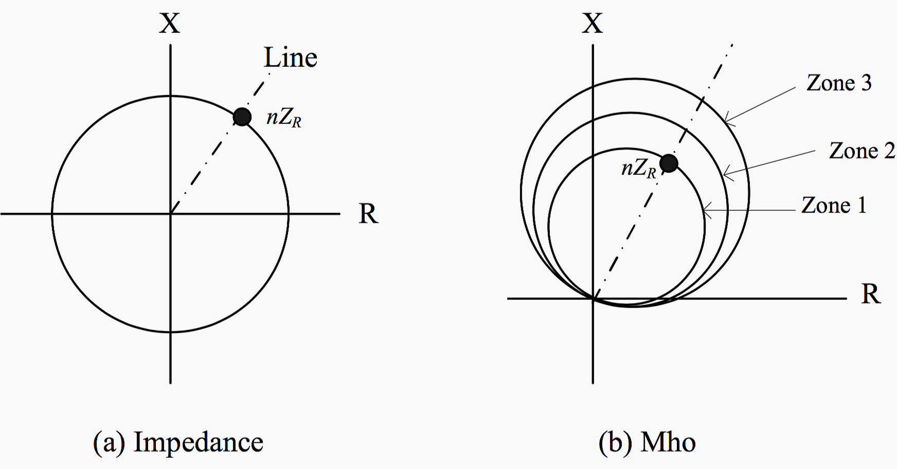
As an illustration in conjunction with the figure, suppose a fault arose, the voltage at relay will be lower or the current will be greater compared to the values for steady state load condition. Thus, distance relays activate when relay’s apparent impedance decreases to any value inside the parametric circle.
For this reason, the impedance of the line after the fault can also be used to find the location of the fault.
Like several engineering constructs, a backup is employed for redundancy. A minimum of two zones are necessary for primary protection of distance relays to address the faults at the far end of the protected line section near the adjacent bus.
The key difference between the two redundant units is in the time delay. The unit covering Zone 1 would operate instantaneously whereas the unit designated in Zone 2 would have an added time delay between fault signaling and operation. Also, by modifying either the restraint and/or operating quantities, the relay operating circles can be shifted as shown in Figure 2b.
In some applications, a further setting (Zone 3) is included, which is greater than Zone 2 setting. For a fault generated in Zone 1, Zone 3’s operation occurs after a longer time delay than that associated with the Zone 2. Therefore, the delay acts as a temporal tolerance for the protective schemes within the fault zone.
The delayed operation will trigger if the tolerance is exceeded.
Hence, this setting provides a form of back up protection. Figure 3 depicts protection zones of distance relays.
Typically, Zone 1 is set in range of 85% to 95% of the positive-sequence of protected line impedance. Zone 2 is set to approximately 50% into the adjacent line, and 25% into the next two lines for Zone 3 as described in. The operation time for Zone 1 is instantaneous whereas Zone 2, and Zone 3 are labeled T2 and T3, respectively.

Most of today’s microprocessor-based relays implement multi-functional protection features. They are considered as a complete protection package in a single unit.
In case of line protection via distance protection schemes, microprocessor-based protective relays also provide:
- Overcurrent protection,
- Directional overcurrent protection (for selectivity in case of multiple parallel lines),
- Under/over voltage protection,
- Breaker failure protection (in case the breaker fails to trip even after receiving the trip command), etc.
Figure 4 shows the connection of a distance relay for line protection.

Go back to protective relays implementations ↑
3. Transformer Protection
Each transformer unit can be protected by a differential relay. The protection principle of this relay is to compare the current inputs at both are high and low voltage sides of the transformer.
Under normal conditions or external faults (also keeping into consideration of the transformer’s turn ratio), the current entering the protected unit would be approximately equal to that leaving it. In other words, there is no current flow in the relay under ideal conditions unless there is a fault in the protected unit.

Moreover, microprocessor-based protective relays incorporate other protection functions such as thermal overload (which tracks the thermal condition of the windings) and over/under frequency relays.
Figure 5 shows the connection of a differential relay for transformer protection.
Go back to protective relays implementations ↑
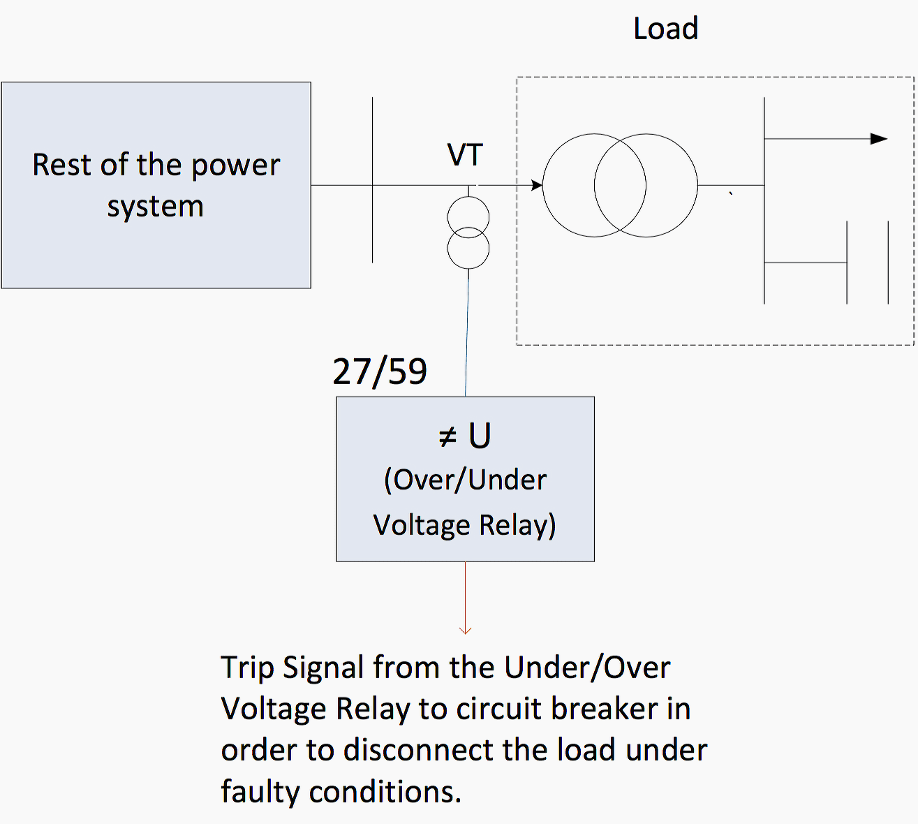
4. Load protection
Electrical loads are commonly sensitive to the voltage variations which can cause serious load damages when high voltage fluctuations arise. In that case, loads can be protected by using over/under voltage protective relays. Figure 6 shows the connection of over/under voltage relay for load protection.
Go back to protective relays implementations ↑
Summary // Protection schemes
Table 1 summarizes all the protection schemes that are designed for the primary power system components discussed above. The table also states the required inputs for the relay to perform each particular protection function and the output parameters from relay in order to generate a trip command.
Table 1 – Protection schemes for common system components
| Component | Relay Type | ANSI code | Operating Principle | Input Parameters | Output Parameters |
| Generator | Out-of-Step relay | 78 | Relay tracks the impedance by detecting the variations of the voltage/current. The variations is small during normal conditions however it changes nearly stepwise in the case of fault conditions. This means that the impedance is changed abruptly. | Current and Voltage (V,I) | Impedance (Z=V/I) |
| Transformer | Differential relay | 87 | Protects the transformer from internal faults by taking the current inputs from both primary and secondary side of the transformer. The sum of these currents (taking into consideration transformer turns ratio) is zero under normal conditions or external faults but not equal to zero in case of fault conditions. | Currents from primary and secondary side (Iprimary, Isecondary) | Current (I) |
| Transmission line | Distance protection | 21 | A fault in a transmission line will result in the decrease of line impedance which is compared with a pre-defined threshold value. The trip signal will be sent to the breaker if the measured impedance is smaller than the threshold. | Current and Voltage (V,I) | Impedance (Z=V/I) |
| Overcurrent protection | 50/51 | A fault in a transmission line will result in the increase of current passing through the line which is compared with a pre-defined threshold value. The trip signal will be sent to the breaker if the measured current exceeds the threshold. | Current (I) | Current (I) | |
| Load | Under/Over voltage protection | 27/59 | A fault at the load bus will vary the terminal voltage. The measured voltage is compared with pre-defined threshold value. The trip signal will be sent to the breaker if it is lower / greater compare to the threshold. | Voltage (V) | Voltage (V) |
Go back to protective relays implementations ↑
Reference // Power System Protective Relaying: basic concepts, industrial-grade devices, and communication mechanisms by Rujiroj Leelaruji and Dr. Luigi Vanfretti
Related electrical guides & articles


Edvard Csanyi
Hi, I'm an electrical engineer, programmer and founder of EEP - Electrical Engineering Portal. I worked twelve years at Schneider Electric in the position of technical support for low- and medium-voltage projects and the design of busbar trunking systems.I'm highly specialized in the design of LV/MV switchgear and low-voltage, high-power busbar trunking (<6300A) in substations, commercial buildings and industry facilities. I'm also a professional in AutoCAD programming.
Profile: Edvard Csanyi

I think there is a correction in the generator protection scheme given in the table (Table 1 – Protection schemes for common system components). To measure the out of step characteristics under faulty condition of generator the desired inputs are the voltage,current and the phase angle between them and the output will have to be some phase angle corresponding to load angle of the synchronous machine and from this we could compare the frequency of generation (which is a inverse proportional of load angle) and the current at the bus.
This article is very helpful in understanding basics of protection schemes in a easy way.Thanks for your article.
I am testing engineer of electrical switchgear and I like your article very much, it has very useful information,
Thank you
Distance propection only is efficient for long overhead lines.
The distinction between “short” and “long” overhead lines is based on a comparison between the inductance and the resistance and capacitance of the overhead line.
When both resistance and capacitance are negligible when compared with the inductance, the over head line is considered “short” (usually l ≤ 80-100 km).
For short lines differential protection with pilot wires is more efficient.
By contrast, distance protection with polygonal impedance characteristics are highly flexible in terms of fault impedance coverage for both phase and earth faults.
For this reason, nowadays most distance relays offer this form of characteristic.