
Estimated Study Time: 11 minutes
Earth leakage current
All installations have an earth leakage current that is mainly due to the conductor’s capacitive leakage and to anti-parasitic or EMI filtering capacitors, for example class I equipment. The sum of these leakage currents may cause highly sensitive residual protection – RCDs to trip. Tripping becomes possible from I∆n/2 without it endangering safety to personnel.
 Twelve installation tips for a good implementing of RCD in electrical network
Leakage currents can be limited by:
- Using class II equipment,
- Isolating transformers,
- Limiting the number of receptors protected by the same RCD.
Installation tips for residual protection
Let’s discuss now about installation tips for correct implementing of residual protection:
- Improving RCD performance
- Indication of test conditions of differential devices
- Choosing a differential device according to the protection to be provided
- Choosing a differential device in IT load
- Choosing a differential device according to auxiliary power supply principles
- Characteristics of a differential device with auxiliary source
- Precautions when installing toroids on armoured cables
- Choosing class of differential devices according to loads
- “Industrial” loads
- Speed variator type loads
- Grouping of uses according to load type
- Signalling or pre-alarm of a leakage or fault
1. Improving RCD performance
1.1 Implementing at the origin of a TT installation
At the origin of a TT installation (and only in this case), it is possible to replace the detection toroid placed around live conductors by a single toroid linking the HV/LV transformer neutral to the earth.
This arrangement improves immunity to disturbances and has the advantage of being more economical.

1.2 Increasing immunity to disturbances of a toroid
Increasing immunity to disturbances of a toroid by:
- Symmetrical arrangement of the phase conductors around the neutral conductor,
- Using a toroid with a diameter of at least equal to twice that of the circle formed by conductors: D ≥ 2d,
- Possible addition of a magnetic shield, with a height at least equal to 2D.
Where:
- d is the centring of the cables in a toroid guarantees the local non-saturation of the toroid. A saturated toroid causes spurious trippings.
- L is distance between the toroid and the bend in the cables.
2. Indication of test conditions of differential devices
Complementary marking should be provided to indicate to the user that the test must be activated regularly (every 3 to 6 months is recommended).
3. Choosing a differential device according to the protection to be provided
Standard NF C 15100 § 531.2.3 stipulates a choice depending on the type of protection to be provided:
- Protection against indirect contact (sensitivity to be chosen depending on admissible contact voltage),
- Complementary protection against direct contact (I∆n 30 mA),
- Protection against fire risk (I∆n 300 mA).
4. Choosing a differential device in IT load
Standard NF C 151 00 § 531.2.4.3 – To avoid spurious tripping of RCDs protecting against indirect contact, for average sensitivity RCDs the device’s rated residual differential current (I∆n) must be higher than double the value of the leakage current (If) that flows during a first fault (I∆n > 2 x If).
5. Choosing a differential device according to auxiliary power supply principles
The level of operator skill and the operational purpose of the installation will, according to standard IEC 60364. determine the choice of the differential protection devices depending on the type of operation linked to the power supply principle.
| Type of differential device | Possible choice depending on type of installation | |
| Uninformed personnel (BA1) | Tried and checked by personnel at least informed (BA4) | |
| With auxiliary source independent of the network | NO | YES |
| Operating independently of the network voltage | YES | YES |
| With operation dependent on the network voltage or on any fail-safe auxiliary source | NO | YES |
| With operation dependent on the network voltage without a fail-safe | NO | YES except PC 16 A circuits |
| With operation dependent on the voltage of an auxiliary source without a fail-safe | NO | YES except PC 16 A circuits and signalling of an aux. source fault |
Note //
A transformer connected to the network does not constitute an auxiliary source independent of the network.
6. Characteristics of a differential device with auxiliary source
Characteristics of a differential device with auxiliary source:
- Monitoring independent of the monitored circuit voltage.
- Suited to networks with high and rapid fluctuation.
- Monitoring independent of the load current (surge of non-balanced currents, coupling of inductive loads).
- Better immunity to tripping in cases of transient faults (integration time in the region of 30 ns, whereas a device with its own current risks tripping in a few ms).
7. Precautions when installing toroids on armoured cables
Armoured cable: insulate electrically from the connection box, and connect it to earth.
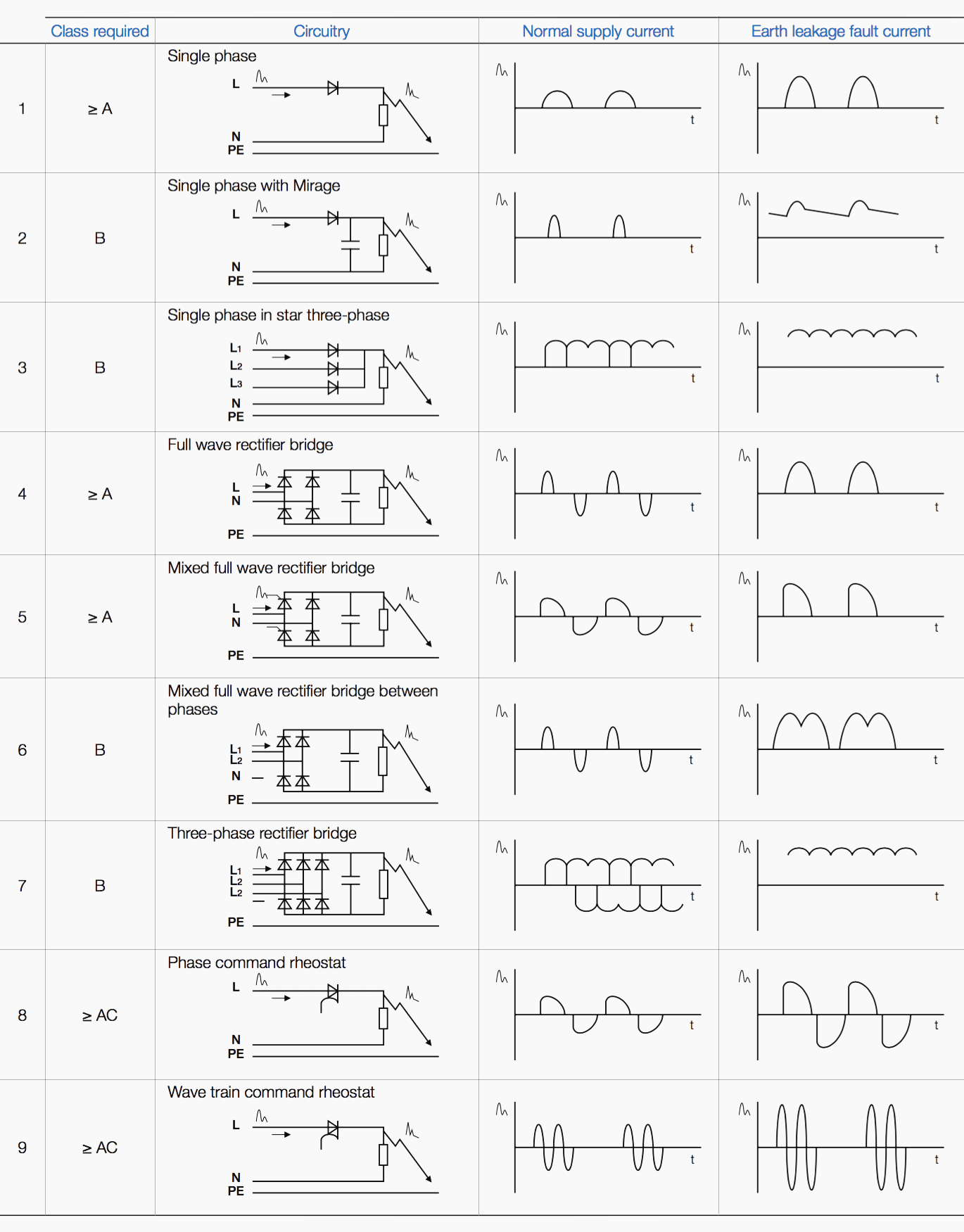
8. Choosing class of differential devices according to loads
Equipment is increasingly fitted with rectifying devices (diodes, thyristors, etc.). Earth fault currents downstream of these devices have a DC component capable of desensitising the RCD. Differential devices must be of the class suited to the loads.
Standard EN 50178 stipulates the following organisation diagram which defines requirements when using electronic equipment behind a differential device.
Transportable electronic equipment whose rated apparent input power does not exceed 4 kVA, must be designed to be compatible with type A RCDs (protection against direct and indirect contact).
Any electronic equipment which risks generating DC component fault current that risks interfering with the operation of the differential protective devices must be accompanied by a warning label which says so.
Standard EN 61800-5-1 offers a choice of RCD class according to the internal electronics of the receptors.
9. “Industrial” loads
The most common devices are of AC class, but the real situation of industrial installations justifies the use of at least A class devices.
10. Speed variator type loads
As this type of load fluctuates considerably, class B relays, independent of the voltage and current, will be even more particularly suited to prevent risks of non-tripping.
11. Grouping of uses according to load type
Installations must group together the types of devices which cause identical faults. If loads are liable to generate DC components, they must not be connected downstream of devices intended to protect loads that generate, in fault, only AC or pulsed rectified components.
12. Signalling or pre-alarm of a leakage or fault
In installations where continuity of operation is imperative and where the safety of property and people is particularly at risk, insulation faults constitute a major risk that it is particularly important to take into account.
The signalling function may be performed in two ways:
First way – The automatic breaking of the power supply for imperative reasons of protection (protection against direct and indirect contact, or limiting the leakage current) is provided by differential devices, the signalling function may be provided by the pre-alarm relays which are incorporated in certain differential relays.
Second way – The automatic breaking of the power supply for imperative reasons of protection (protection against direct and indirect contact, or limiting the leakage current) is provided by other devices, such as for example, protection devices against overcurrents.
The relay contact alarm may therefore be used only for signalling a differential current.
Preventive signalling of insulation faults provides optimisation of an electrical installation by:
- Anticipating a machine repair before the process is stopped or on fault,
- Locating insulation faults in TNS neutral loads,
- Preventing risks of fire, explosion, etc.,
- Anticipating the operation of an overcurrent protection device and thus avoiding the replacement of the fuse or the ageing of the circuit breaker,
- Controlling the leakage currents and thus reducing the homopolar currents in protection circuits, and reducing the generating of particularly disturbing electromagnetic fields,
- etc.
Reference // Application Guide 2011 by Socomec
Related electrical guides & articles


Edvard Csanyi
Hi, I'm an electrical engineer, programmer and founder of EEP - Electrical Engineering Portal. I worked twelve years at Schneider Electric in the position of technical support for low- and medium-voltage projects and the design of busbar trunking systems.I'm highly specialized in the design of LV/MV switchgear and low-voltage, high-power busbar trunking (<6300A) in substations, commercial buildings and industry facilities. I'm also a professional in AutoCAD programming.
Profile: Edvard Csanyi

Good information on the AC for house protection
Edvard,
Comments: Section 3 (“Choosing a device”). If we’re protecting against indirect contact, the criterion shouldn’t be “admissable contact voltage”, but the resulting current through the victim. The usually specified device rating is 30 mA. But he accepted limit for ‘let-go’ current at 50-60Hz is 10mA. If, for whatever reason, someone is conducting more than this, but less than 30mA, he could be unable to let go & would have to endure the shock indefinitely. That hardly constitutes “protection” does it.
Section 6.4 (Better immunity to tripping…) Integration time of 30 nanoseconds? really?? This would give no immunity at all against transients. (We must hope the writer meant 30ms).
Section 8 Flowchart: The criterion for ‘power’ level doesn’t make sense. The writer probably meant
” 4kVA” for the right-hand branch. Personally, I don’t see any reason not to fit DC-sensitive devices throughout – apart from slight extra cost. We can’t always forsee whether an office (or even a domestic) installation might gradually acquire appliances that produce a significant DC earth leakage -especially during a fault- that might fail to trip an ‘AC-sensitive-only’ device.
Regards, David.